High-efficiency waste incineration waste heat utilization power generation system

A technology of waste incineration and power generation system, which is applied in the direction of preheating, incinerator, combustion method, etc., can solve the problems of increasing corrosion risk, corrosion, etc., and achieve the effect of increasing corrosion risk, increasing surface temperature, and improving power generation efficiency

Pending Publication Date: 2022-03-25
SHANGHAI SUS ENVIRONMENT
View PDF4 Cites 0 Cited by
  • Summary
  • Abstract
  • Description
  • Claims
  • Application Information

AI Technical Summary

Problems solved by technology

However, in waste incineration boilers, the arrangement of reheating tube bundles has the same corrosion problem as the superheater, and will even further increase the flue gas temperature at the inlet of the superheater due to the increased heat absorption requirements of the reheating tube bundles, increasing the risk of corrosion

Method used


Image

  • High-efficiency waste incineration waste heat utilization power generation system
  • High-efficiency waste incineration waste heat utilization power generation system
  • High-efficiency waste incineration waste heat utilization power generation system

Examples


Embodiment Construction

[0032] Embodiments of the present invention are described in detail below, examples of which are shown in the drawings, wherein the same or similar reference numerals designate the same or similar elements or elements having the same or similar functions throughout. The embodiments described below by referring to the figures are exemplary only for explaining the present invention and should not be construed as limiting the present invention.

[0033] In the description of the present invention, it should be understood that the orientation descriptions, such as up, down, front, back, left, right, etc. indicated orientations or positional relationships are based on the orientations or positional relationships shown in the drawings, and are only In order to facilitate the description of the present invention and simplify the description, it does not indicate or imply that the device or element referred to must have a specific orientation, be constructed and operated in a specific ...


PUM


Abstract

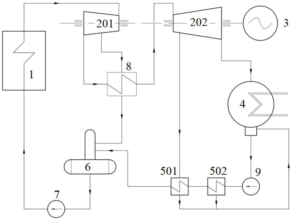
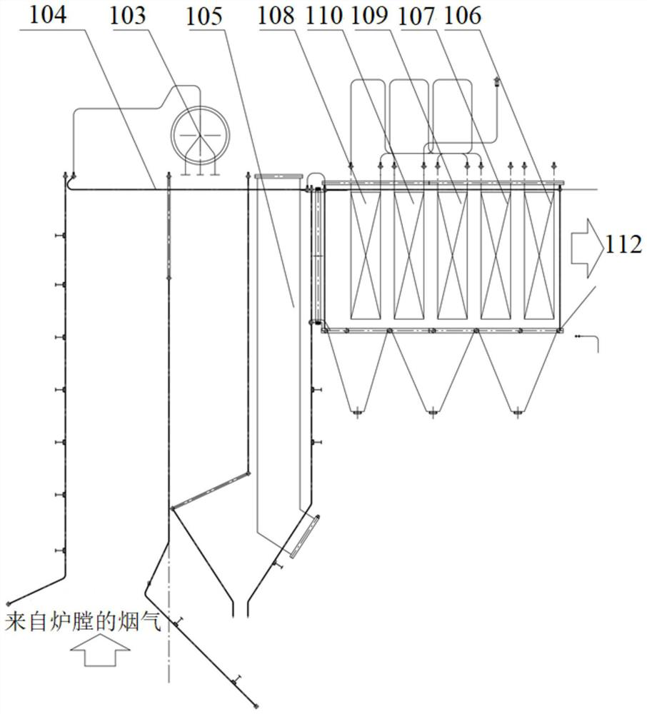
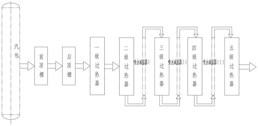
The invention provides a high-efficiency waste incineration waste heat utilization power generation system. The high-efficiency waste incineration waste heat utilization power generation system comprises a power generator, a waste heat boiler, a steam turbine high-pressure cylinder, a dehumidification reheater, a steam turbine low-pressure cylinder, a condenser, a condensate pump, a heat regeneration system, a deaerator and a water feeding pump, heat of high-temperature flue gas of the incinerator is transmitted to feed water through the waste heat boiler, medium-temperature ultrahigh-pressure steam is generated, and in the process, corrosion prevention optimization and boiler water circulation optimization must be conducted on the waste heat boiler. Medium-temperature ultrahigh-pressure steam has certain humidity after being used as main steam to be connected into a high-pressure cylinder of a steam turbine to do work, water in exhaust steam is removed through a dehumidification reheater, heat of secondary extraction steam of the high-pressure cylinder is absorbed, and the medium-temperature ultrahigh-pressure steam enters the low-pressure cylinder to do work after reaching steam inlet parameters of the low-pressure cylinder. Dead steam enters the condenser to release heat, becomes condensed water and returns to the waste heat boiler after being subjected to heat regeneration through the heat regeneration system and deoxygenization through the deaerator, and the power generation efficiency is improved on the premise that the surface temperature of a heat exchanger is not greatly increased and the corrosion risk is not greatly increased.

Description

technical field [0001] The invention belongs to the technical field of thermal power generation, in particular to a high-efficiency power generation system utilizing waste heat from waste incineration. Background technique [0002] Garbage incineration is a common domestic waste disposal method. In waste incineration power generation, the high-temperature flue gas obtained from incinerating waste is usually used to heat feed water to generate steam. For this reason, the incinerator will be equipped with a waste heat boiler. The waste heat boiler is composed of heat exchange tube bundles such as water-cooled walls, evaporators, superheaters, and economizers. The gas exchanges heat to the soda water during the flow. Domestic project steam is usually superheated to a temperature of about 400°C to 485°C, and a pressure of about 4.0MPa to 7.0MPa. [0003] Domestic efforts have been made to improve the waste heat utilization efficiency of waste incineration power generation, an...

Claims


Application Information

Patent Timeline
Patent Type & Authority Applications(China)
IPC IPC(8): F01D15/10F01K11/02F01K27/00F23G5/46F22D1/50F22D1/02F22D11/06
CPCF01D15/10F01K11/02F01K27/00F23G5/46F22D1/50F22D1/02F22D11/06Y02E20/12
Inventor 龙吉生钱达蔚李建平倪鲲鹏王玮严浩文郝章峰潘浩泉杨灿何秋德
Owner SHANGHAI SUS ENVIRONMENT
Why Eureka
Try Eureka