Construction method for erecting overhead line system power supply line based on unmanned aerial vehicle technology

A construction method and power supply line technology, which is applied in the construction field of erecting catenary power supply lines based on UAV technology, can solve the problems of unsatisfactory railway power supply lines, high safety factor, high voltage level of railway power supply lines, etc., and achieve guaranteed strength and Reliability and safety of power supply, avoiding tree felling, and enhancing the effect of service life

Pending Publication Date: 2022-03-29
CHINA CREC RAILWAY ELECTRIFICATION BUREAU GRP +1
View PDF2 Cites 0 Cited by
  • Summary
  • Abstract
  • Description
  • Claims
  • Application Information

AI Technical Summary

Problems solved by technology

The existing patent CN 211338261U, a kind of pay-off device for railway power supply erection, can only meet the demand of electric traction, and cannot meet the demand of high-altitude deployment
CN106786311A Barrier-free power supply line erection system for track fields is only suitable for agricultural track fields. Steel cables are used instead of pillars. Due to the high voltage level and high safety factor of railway power supply lines, this method cannot meet the needs of railway power supply lines
[0005] The schematic diagram of manual erection of catenary power supply lines at this stage is as follows: figure 1 As shown, this method meets the construction requirements in open areas such as plains. When it is in hills and mountains, a large number of trees need to be cut down to meet the needs of manual erection, and it cannot meet the needs of manual erection when crossing rivers.
At the same time, it cannot meet the needs of multiple power supply lines being erected at the same time

Method used


Image

  • Construction method for erecting overhead line system power supply line based on unmanned aerial vehicle technology
  • Construction method for erecting overhead line system power supply line based on unmanned aerial vehicle technology
  • Construction method for erecting overhead line system power supply line based on unmanned aerial vehicle technology

Examples


Embodiment 1

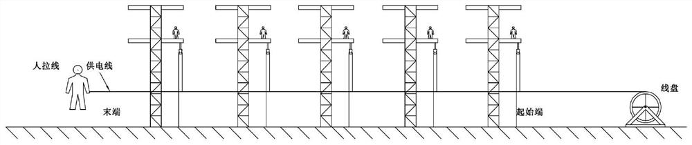
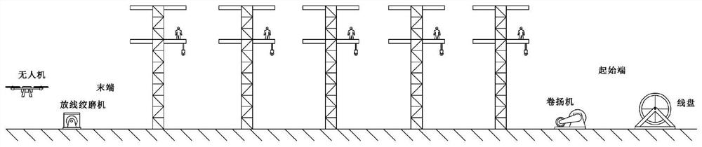
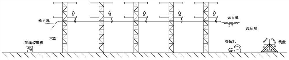
[0025] This embodiment provides a construction method for erecting catenary power supply lines based on unmanned aerial vehicle technology, referring to Figure 6 , which includes the following steps, S1 refers to figure 2 , firstly carry out the preparatory work of the whole construction method, that is, the layout of the equipment, place the unmanned aerial vehicle and the payout winch at the end of the anchor section that needs to be released, and set the winch at the beginning of the anchor section that needs to be released, corresponding to the In the accompanying drawings, the left side is the end of the anchor section that needs to be released, and the right side is the beginning of the anchor section that needs to be released. A steel wire rope is wound on the pay-off winch mill. Fix the reel where the power supply line is located on the pay-off bracket, pull out the end of the wire to prepare for the release, and place it at the beginning of the anchor section that ...

Embodiment 2

[0043] The difference between embodiment 2 and embodiment 1 is that in step S5, when lifting the anchor, this embodiment has two power supply lines, and the anchor connection mode of the two power supply lines is Z-10 four-legged right-angle hanging board, 18 pestle ring rods, Suspension insulator (XWP2-70), WS-10 double bowl head hanging plate, L-1240 type connecting plate and 2* pre-twisted wire tension clamps are connected, and the above-mentioned components are connected. The connection process and method are as follows: The technique is well known to those skilled in the art.

Embodiment 3

[0045] The difference between Example 3 and Example 1 is that in step S5, the suspension connection mode of a single power supply line is a long suspension ring (with ball suspension), 4 pieces of pestle head suspension insulators, suspension clamps (CGU-5A) and pre-twisted The connection of the type short protective strip, the connection of the above-mentioned components, the connection process and method are well known to those skilled in the art. Tighten the hook bolt at the same time, retract the sleeve and the pay-off pulley.


PUM

PropertyMeasurementUnit
Cross-sectional areaaaaaaaaaaa

Abstract

The invention relates to a construction method for erecting a catenary power supply line based on an unmanned aerial vehicle technology, which comprises the following steps: S1, placing an unmanned aerial vehicle and a pay-off winching machine wound with a steel wire rope at the tail end of an anchor section needing pay-off, and arranging a winch at the initial end of the anchor section needing pay-off, setting a pulley at the position of a preset pillar on which the power supply line is to be erected by an operator; s2, the unmanned aerial vehicle drives the traction rope to sequentially pass through the pulleys and then wind the traction rope on a winch, and a worker places the traction rope on the pulleys; s3, the tail end of the traction rope is connected with the starting end of the steel wire rope, the winch drags the traction rope so as to drag out the steel wire rope on the paying-off winching machine, and a power supply line is connected with the steel wire rope; s4, the power supply line is spread through traction of the paying-off winching machine; and S5, sequentially carrying out anchor weighing, winching machine traction, power supply line sag measurement, anchor falling, wire fixing and adjustment. The overhead line system can meet the requirement for erecting a plurality of overhead line system power supply lines in mountainous areas, hilly areas and river crossing positions.

Description

technical field [0001] The invention belongs to the technical field of construction methods for catenary power supply lines, and in particular relates to a construction method for erecting catenary power supply lines based on unmanned aerial vehicle technology. Background technique [0002] With the continuous development of my country's economy, people's demand for electricity is gradually increasing. As an important part of my country's economic development, electric power engineering enterprises can promote the development of social economy is the construction of power engineering by the construction technology of distribution network overhead lines. However, in the process of engineering construction, the construction technology is affected by many aspects, and many problems have appeared in the actual construction process. Therefore, perfecting the construction technology is of great significance to the rapid development of today's electric power enterprises. At the sam...

Claims


Application Information

Patent Timeline
IPC IPC(8): H02G1/02H02G1/04B64C39/02B60M1/28
CPCH02G1/02H02G1/04B64C39/02B60M1/28B64U2101/00
Inventor 李茂才王敬渊王先铎王胜利吴亮邓德欣赵波
Owner CHINA CREC RAILWAY ELECTRIFICATION BUREAU GRP
Why Eureka
Try Eureka