Supercharge Your Innovation With Domain-Expert AI Agents!

A combined multi-channel diffuser of a gas turbine and its diffuser intake structure

A gas turbine and air intake structure technology, which is applied in the combustion chamber, combustion method, combustion equipment, etc., can solve the problems of air pressure deceleration performance and the overall length cannot be taken into account, and achieve the effect of improving the diffusion efficiency

Active Publication Date: 2022-07-08
成都中科翼能科技有限公司
View PDF18 Cites 0 Cited by
  • Summary
  • Abstract
  • Description
  • Claims
  • Application Information

AI Technical Summary

Problems solved by technology

[0006] In order to solve the problem that the air pressure deceleration performance and the overall length of the diffuser structure of the existing gas turbine cannot be balanced, this scheme provides a combined multi-channel diffuser and its diffuser intake structure for the gas turbine

Method used


Image

  • A combined multi-channel diffuser of a gas turbine and its diffuser intake structure
  • A combined multi-channel diffuser of a gas turbine and its diffuser intake structure

Examples


Embodiment 1

[0033] like Figure 1 to Figure 2 As shown, this embodiment designs a diffuser air intake structure of a gas turbine, which is used to diffuse and decelerate the air entering the casing 3 of the gas turbine combustion chamber.

[0034]With the development of the structure of the gas turbine engine, its rotational speed is getting faster and faster, which makes the airflow velocity at the outlet of the compressor inside the gas turbine very large, and when such a high-speed airflow enters the combustion chamber of the gas turbine, it will Affects ignition combustion in the combustion chamber. Therefore, a corresponding diffuser structure is designed to diffuse and decelerate the air entering the combustion chamber to ensure that the air flow velocity is generally reduced to five times the air velocity at the compressor outlet before reaching the combustion chamber for combustion. It can form a stable outlet flow field, so as to ensure the stable combustion of the combustion ch...

Embodiment 2

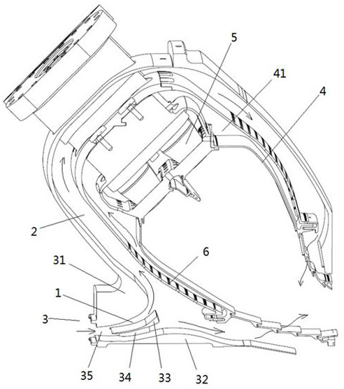
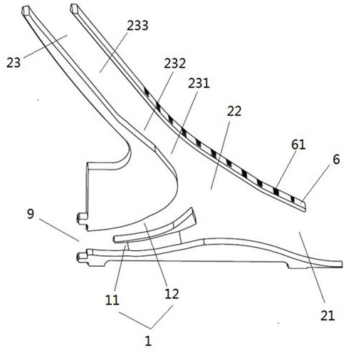
[0046] like Figure 1 to Figure 2 As shown, this embodiment designs a combined multi-channel diffuser for a gas turbine, and the combined multi-channel diffuser is installed on the combustion chamber casing 3 of the gas turbine, as shown in figure 1 shown.

[0047] The combustion chamber casing 3 is provided with structures such as a flame tube 4 and a fairing 6. The flame tube 4 is an annular groove-shaped structure as a whole, and the bottom of the flame tube 4 is used to install the premixer 5. The notch of the flame tube 4 is the outlet of the flame tube 4; the fairing 6 is covered outside the flame tube 4, and an outer wall cooling channel 41 for cooling the wall of the flame tube 4 is formed between the two; The fairing 6 is provided with ventilation holes 61 .

[0048] The combined multi-channel diffuser in this embodiment includes a diffuser outer ring 31 , a diffuser inner ring 32 , a flow divider 33 and the diffuser air intake structure in Embodiment 1. The diffuse...


PUM


Abstract

The invention belongs to the technical field of gas turbines, and in particular relates to a combined multi-channel diffuser of a gas turbine and a diffuser air intake structure thereof, which are used to diffuse and decelerate the air entering a combustion chamber casing of the gas turbine, including a pre-diffusing channel and a sudden diffusion diffuser channel; an air inlet is provided on the inner side of the ring of the combustion chamber casing, and a flame tube is installed in the combustion chamber casing; the pre-diffusing channel includes a plurality of branch channels and is arranged at the air inlet , so as to divide and diffuse the air entering the air inlet; the sudden diffuser channel is arranged in the casing of the combustion chamber and can drain the air to the inside and outside of the ring of the flame tube; the sudden diffuser channel and the The pre-diffusing passage communicates and re-diffuses the air sent from the pre-diffusing passage. The combined diffusing structure improves the effect of diffusing and decelerating air within a short distance, and ensures that the high-speed airflow introduced from the compressor outlet can enter the combustion chamber uniformly and stably for combustion.

Description

technical field [0001] The invention belongs to the technical field of gas turbines, and in particular relates to a combined multi-channel diffuser of a gas turbine and a diffuser intake structure thereof. Background technique [0002] Gas turbine is a gas turbine engine, which is an internal combustion power machine that converts the energy of gas into useful work. It is widely used in many fields, such as: used in the field of civil power generation or used as a power unit in aircraft or large ships middle. The working process of the gas turbine is as follows: the compressor continuously sucks in air from the atmosphere and compresses the air; the compressed air enters the combustion chamber, and is mixed with the gas injected into the combustion chamber and then combusted to become high-temperature gas, and then the high-temperature gas flows into the combustion chamber. It expands to the gas turbine to do work, and uses high-temperature gas to drive the turbine to rotat...

Claims


Application Information

Patent Timeline
Patent Type & Authority Patents(China)
IPC IPC(8): F23R3/26F23R3/42
CPCY02T50/60
Inventor 杨治王鸣范珍涔刘宝琪王少波陈柳君代茂林王梁丞王龙刘印
Owner 成都中科翼能科技有限公司
Features
  • R&D
  • Intellectual Property
  • Life Sciences
  • Materials
  • Tech Scout
  • Unparalleled Data Quality
  • Higher Quality Content
  • 60% Fewer Hallucinations
Learn More