Wire drawing system for steel wire drawing

A wire drawing and steel wire technology, applied in the direction of wire drawing dies, etc., can solve the problems of steel wire surface quality and mechanical properties degradation, 4-point angular contact bearings are easily damaged due to high force, and the wear of the single-side pass of the wire drawing die is aggravated. The effect of water leakage failure, solving the problem of broken screws, improving surface quality and mechanical properties

Pending Publication Date: 2022-04-05
JIANGYIN FASTEN STEEL PRODS +1
View PDF0 Cites 2 Cited by
  • Summary
  • Abstract
  • Description
  • Claims
  • Application Information

AI Technical Summary

Problems solved by technology

When the phosphating wire rod on the pay-off rack of the wire drawing machine moves from the rear end to the front end, the rear end of the pay-off rack needs to be hoisted by a crane. For the drawing drawing machine pay-off schematic diagram, see figure 1 , because the wire rod will touch the front bearing cover plate, it is easy to scrape off the phosphating layer on the surface of the wire rod during work, which will affect the quality of the wire rod, and the shear force of the bent wire rod will act on the bearing cover plate to cause fixation The screws are often broken or even, and the holes of the fixing screws are slippery, resulting in a heavy workload for the mechanics and difficult maintenance, and a long maintenance time
[0003] The wire roller on the front wire roller group of the existing pay-off rack is short, see figure 2 During production, the wire rod often escapes and is easily broken, which affects production efficiency. The steel wire ejection also poses a safety hazard to the equipment, and the wire roller on the wire roller roll is stressed and easily damaged, and only one end of the wire roller is fixed on the steel plate by a screw. On the other hand, the shaft hole of the fixed guide roller will become larger after being stressed, so that the guide roller will shake or even fall, posing a safety hazard
[0004] Existing drawing dies include rotating mold boxes and fixed mold boxes, which have the following defects: the tangential direction of the steel wire is not concentric with the mold when it comes out of the drawing die mouth and is put on the reel
On the one hand, it causes aggravated wear of the unilateral pass of the wire drawing die, making the pass elliptical; on the other hand, it causes uneven drawing deformation in the circumferential direction of the steel wire, making the ellipticity of the steel wire out of tolerance, and at the same time causing the surface quality of the steel wire and decrease in mechanical properties
Now the metal products industry uses a rotating die to rotate the drawing die slowly to eliminate the oval wear tendency of the drawing die during the drawing process, but the existing rotating die rotates too fast and is easy to wear, and the lubricating powder easily enters the gear cavity Contact bearings are subject to large forces and are easily damaged, and there are many faults, which affect the service life of the rotary mold
When the above-mentioned defects break down, the maintenance work takes a long time, which reduces production efficiency and increases maintenance costs

Method used


Image

  • Wire drawing system for steel wire drawing
  • Wire drawing system for steel wire drawing
  • Wire drawing system for steel wire drawing

Examples


Embodiment 1

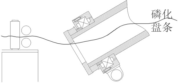
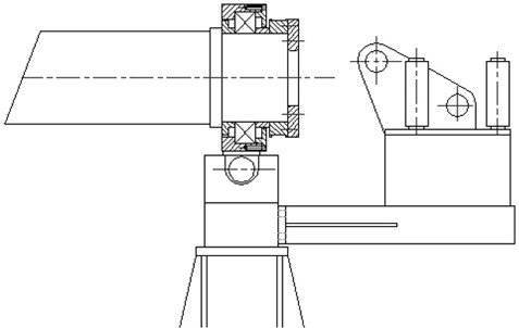
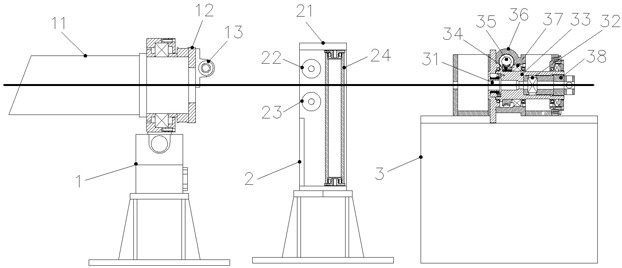
[0028] refer to Figure 3-6 , image 3 What is drawn is a structural schematic diagram of a wire drawing system used for steel wire drawing. As shown in the figure, the present invention relates to a wire drawing system for steel wire drawing, which includes a wire drawing machine, a pay-off frame 1, a guide roller frame 2 and a rotating wire drawing device 3 arranged in sequence.

[0029] The pay-off rack 1 includes a support and a pay-off channel 11 arranged on the support, one end of the pay-off channel 11 is connected to the wire drawing machine, and the port at the other end is provided with a bearing cover plate 12; one part of the bearing cover plate 12 One side is the pay-off channel 11, and the other side is provided with a pay-off roller 13, and the pay-off roller 13 is close to the bearing cover plate 12, is arranged on the top of the steel wire outlet, is fixed on the machine base or on the bearing cover plate 12, and The centerline of the pay-off roller 13 is pe...


PUM


Abstract

The invention discloses a wire drawing system for drawing a steel wire. The wire drawing system comprises a wire drawing machine, a guide roller frame and a rotary wire drawing device which are arranged in sequence, the wire drawing machine comprises a pay-off rack, the pay-off rack comprises a machine base and a pay-off channel arranged on the machine base, one end of the pay-off channel is connected with the wire drawing machine, and a bearing cover plate is arranged at a port of the other end of the pay-off channel; a pay-off roller is arranged on one side of the bearing cover plate; the guide roller frame comprises a machine base, a fixed box body arranged on the machine base and a guide roller set, the guide roller set is arranged in the fixed box body, and a steel wire passing opening is formed between guide rollers in the guide roller set; the rotary wire drawing device comprises a base and a box body arranged on the base, a barrel is arranged in the box body, a wire drawing cavity and a wire drawing die are sequentially arranged in the barrel body, the barrel body is sleeved with a worm gear, and the worm gear is connected with a worm. The rotating service life is prolonged, the workload of machine maintenance workers is reduced, the maintenance cost is reduced, the stopping maintenance time is shortened, and the working efficiency is improved.

Description

technical field [0001] The invention relates to the technical field of steel strand production equipment, in particular to a wire drawing system for steel wire drawing. Background technique [0002] The production of steel strands first draws the raw material wire rods through a wire drawing machine. The mold box is one of the main parts of the wire drawing process. Drawing steel wires requires a drawing die to make the wire diameter thinner. When the phosphating wire rod on the pay-off rack of the wire drawing machine moves from the rear end to the front end, the rear end of the pay-off rack needs to be hoisted by a crane. For the drawing drawing machine pay-off schematic diagram, see figure 1 , because the wire rod will touch the front bearing cover plate, it is easy to scrape off the phosphating layer on the surface of the wire rod during work, which will affect the quality of the wire rod, and the shear force of the bent wire rod will act on the bearing cover plate to ca...

Claims


Application Information

Patent Timeline
Patent Type & Authority Applications(China)
IPC IPC(8): B21C1/02B21C3/08B21C3/14B21C9/00
Inventor 屠金辉刘长修张世琪曹琪谢建哲赵建刚陶建春严士兴
Owner JIANGYIN FASTEN STEEL PRODS
Why Eureka
Try Eureka