
Temperature sensing circuit, CMOS temperature sensor based on temperature sensing circuit and calibration method of CMOS temperature sensor

A MOS tube and circuit technology, applied in the field of sensors, can solve the problems of difficult design, difficult to achieve ultra-low power consumption, large occupied area, etc., and achieve the effects of simple structure, reduced consumption, and low calibration cost

Active Publication Date: 2022-04-05
INST OF SEMICONDUCTORS - CHINESE ACAD OF SCI
View PDF12 Cites 0 Cited by
  • Summary
  • Abstract
  • Description
  • Claims
  • Application Information

AI Technical Summary

Problems solved by technology

However, the traditional CMOS integrated temperature sensor is difficult to design under advanced technology, occupies a large area, and it is difficult to achieve ultra-low power consumption
This limits the application of traditional CMOS temperature sensors in the fields of thermal management of processors and large SoCs, the Internet of Things, and wireless sensor networks. These application environments require temperature sensors to have characteristics such as small area, low power consumption, and low-voltage power supply.

Method used


Image

  • Temperature sensing circuit, CMOS temperature sensor based on temperature sensing circuit and calibration method of CMOS temperature sensor
  • Temperature sensing circuit, CMOS temperature sensor based on temperature sensing circuit and calibration method of CMOS temperature sensor
  • Temperature sensing circuit, CMOS temperature sensor based on temperature sensing circuit and calibration method of CMOS temperature sensor

Examples


Embodiment Construction

[0034] In order to make the object, technical solution and advantages of the present invention clearer, the present invention will be further described in detail below in conjunction with specific embodiments and with reference to the accompanying drawings.

[0035] At present, there are still some deficiencies in CMOS temperature sensors that use MOS tubes to sense temperature. The two variables of the bias and slope of the linear function are unknown, so two-point calibration is required, and the calibration cost is relatively high; in addition, if the temperature characteristics of the MOS tube working in the strong inversion area are used for temperature sensing, the power consumption of the sensor will also decrease. will rise accordingly.

[0036] Based on the above problems, this disclosure proposes a temperature-sensing circuit, a CMOS temperature sensor based on the temperature-sensing circuit and its calibration method, which realizes the working mode of small curren...


PUM


Abstract

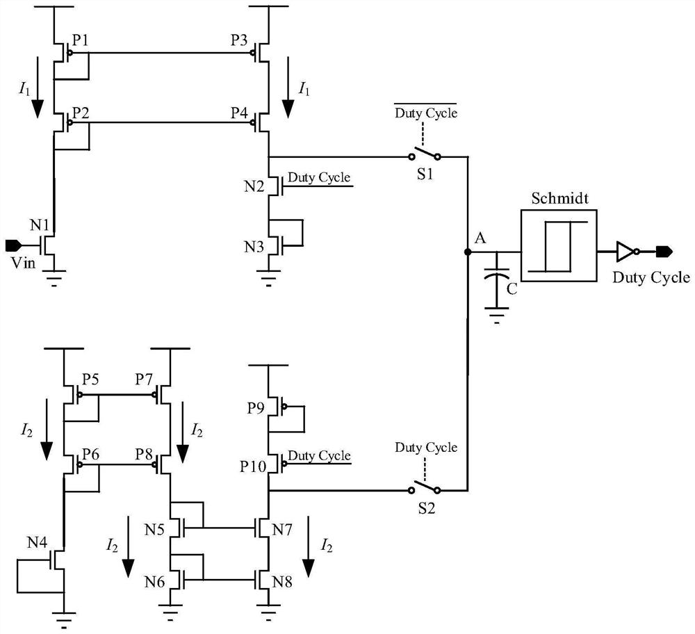
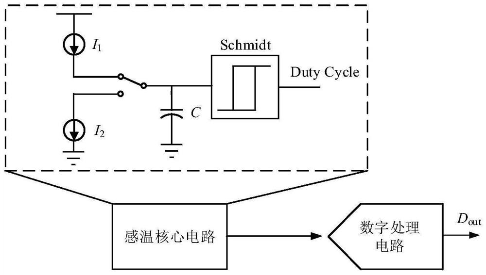
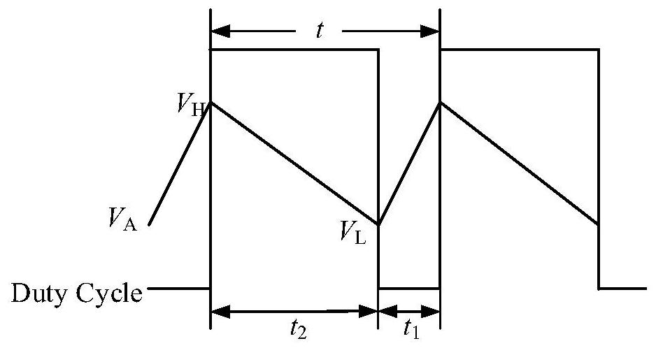
The invention provides a temperature sensing circuit, a CMOS temperature sensor based on the temperature sensing circuit and a calibration method of the CMOS temperature sensor, and the temperature sensing circuit comprises a charging module, the output end of which is used for being connected with the first end of a control switch; the input end of the discharging module is used for being connected with the second end of the control switch; one end of the Schmitt trigger is connected with the control switch, and the Schmitt trigger is used for determining whether to trigger level state conversion according to the voltage value so as to control switching of the control switch; the capacitor is arranged between the control switch and the Schmitt trigger and is used for storing or releasing charges; and the output port is connected to the other end of the Schmitt trigger and is used for outputting a duty ratio signal related to the temperature.

Description

technical field [0001] The invention relates to the technical field of sensors, in particular to a temperature sensing circuit, a CMOS temperature sensor based on the temperature sensing circuit and a calibration method thereof. Background technique [0002] Temperature sensors are widely used in modern industry, medical treatment, transportation, smart home and other fields. With the rapid development of integrated circuits, integrated temperature sensors based on CMOS technology have attracted the attention of academia and industry because of their advantages such as easy system integration, low cost, and direct output of digital signals. [0003] The traditional CMOS integrated temperature sensor uses the temperature characteristics of the base-emitter voltage of the triode to sense the temperature, uses a high-precision analog-to-digital converter (ADC) as the readout circuit, and cooperates with dynamic component matching technology, chopping technology, etc., can reali...

Claims


Application Information

Patent Timeline
Patent Type & Authority Applications(China)
IPC IPC(8): G01K15/00G01K7/00
Inventor 李文昌张天一
Owner INST OF SEMICONDUCTORS - CHINESE ACAD OF SCI
Learn More