Large-current planar transformer assembling equipment and assembling method

A technology for planar transformers and assembly equipment, which is applied in the manufacture of inductors/transformers/magnets, circuits, and electrical components. Improve assembly yield and consistency, improve regularity and efficiency, and reduce assembly difficulty

Pending Publication Date: 2022-04-05
无锡兰迪电子有限公司
View PDF0 Cites 3 Cited by
  • Summary
  • Abstract
  • Description
  • Claims
  • Application Information

AI Technical Summary

Problems solved by technology

[0003] Usually, a planar transformer is implemented with a single multi-layer circuit board, which has a fixed number of turns and a fixed ratio. It can only be used for a single purpose without high compatibility and the assembly process is simple. Due to the structural limitations of the multi-layer circuit board, this structure cannot be realized. Reach high current levels above 50A, planar transformers with composite structure can reach high current levels above 50A, but the composite structure leads to high assembly difficulty requirements, long assembly time, low yield and consistency
[0004] The existing high-current planar transformer assembly equipment has the following disadvantages: the assembly of the pins in the composite structure planar transformer lacks a stable limit structure, resulting in deviation and misalignment during the assembly process

Method used


Image

  • Large-current planar transformer assembling equipment and assembling method
  • Large-current planar transformer assembling equipment and assembling method
  • Large-current planar transformer assembling equipment and assembling method

Examples


Embodiment 1

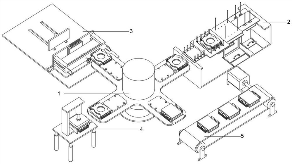
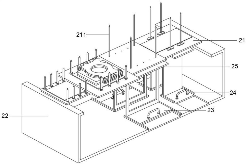
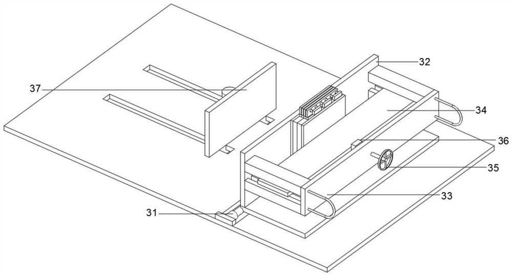
[0033] Such as Figure 1-6 As shown, a high-current planar transformer assembly equipment includes a four-station turntable 1, a coil fixture 2, a coil pin fixture 3 and an overall alignment fixture 4, and one side of the four-station turntable 1 is provided with a conveyor belt for outputting finished transformers 5. The coil fixture 2, the coil pin fixture 3, the overall alignment fixture 4 and the conveyor belt 5 are arranged equidistantly clockwise with the four-station turntable 1 as the center of the circle, and the coil pin fixture 3 is equipped with multiple limit clamps The structure is convenient for coil pin access, and the four stations of the four-station turntable 1 correspond to the assembly steps of the high-current planar transformer, which significantly improves the regularity and efficiency of the assembly, while the assembly of the coil pins At the same time, the clamping structure in the coil pin fixture 3 provides a tight pressure limit on the top and bot...

Embodiment 2

[0043] Such as Figure 1-6 As shown, a high-current planar transformer assembly equipment includes a four-station turntable 1, a coil fixture 2, a coil pin fixture 3 and an overall alignment fixture 4, and one side of the four-station turntable 1 is provided with a conveyor belt for outputting finished transformers 5. The coil fixture 2, the coil pin fixture 3, the overall alignment fixture 4 and the conveyor belt 5 are arranged equidistantly clockwise with the four-station turntable 1 as the center of the circle, and the coil pin fixture 3 is equipped with multiple limit clamps The structure is convenient for coil pin access, and the four stations of the four-station turntable 1 correspond to the assembly steps of the high-current planar transformer, which significantly improves the regularity and efficiency of the assembly, while the assembly of the coil pins At the same time, the clamping structure in the coil pin fixture 3 provides a tight pressure limit on the top and bot...


PUM


Abstract

The invention provides a large-current planar transformer assembling device and method, and relates to the technical field of transformer assembly.The assembling device comprises a four-station rotary table, a coil clamp, a coil pin clamp and an overall alignment clamp, and a conveying belt for outputting transformer finished products is arranged on one side of the four-station rotary table; the coil clamps, the coil pin clamps, the overall alignment clamps and the conveying belt are clockwise arranged at equal intervals with the four-station rotating disc as the circle center, and clamping structures with multiple limiting functions are arranged in the coil pin clamps, so that coil pins can be conveniently connected. Corresponding clamp devices are adopted in the assembling processes of the composite coil body, the composite coil leading-out ends and the transformer body, the assembling difficulty can be reduced, the assembling efficiency can be improved, the assembling yield and consistency can be improved, clamping structures in the coil pin clamps provide pressing and limiting for the top and the two sides of a composition, and the assembling efficiency can be improved. The pins can be conveniently welded and assembled through 90-degree rotation limiting, and the multiple limiting structures enable the pins to be accurately and rapidly assembled.

Description

technical field [0001] The invention relates to the technical field of transformer assembly, in particular to a large current planar transformer assembly equipment and assembly method. Background technique [0002] A planar transformer is a transformer with high frequency, low shape, small height and high operating frequency. It is widely used in power supplies as a component for voltage transformation. [0003] Usually, a planar transformer is implemented with a single multilayer circuit board, which has a fixed number of turns and a fixed ratio. It can only be used for a single purpose without high compatibility. The assembly process is simple. Due to the structural limitations of the multilayer circuit board, this structure cannot be realized. Reaching a high current level above 50A, a planar transformer with a composite structure can reach a high current level above 50A, but the composite structure leads to high assembly difficulty requirements, long assembly time, and l...

Claims


Application Information

Patent Timeline
Patent Type & Authority Applications(China)
IPC IPC(8): H01F41/00H01F41/10
Inventor 潘裕丰
Owner 无锡兰迪电子有限公司
Why Eureka
Try Eureka