Phase encoding method and system based on delay line interferometer

A phase encoding and interferometer technology, applied in the field of phase encoding methods and systems based on delay line interferometers, can solve problems such as complex structures and achieve the effect of reducing components

Active Publication Date: 2022-04-05
HANGZHOU DIANZI UNIV
View PDF6 Cites 0 Cited by
  • Summary
  • Abstract
  • Description
  • Claims
  • Application Information

AI Technical Summary

Problems solved by technology

[0004] However, the structure of the existing phase encoding system is relatively complicated, and the system needs one or more phase modulators controlled by digital signals to introduce phase jumps.

Method used


Image

  • Phase encoding method and system based on delay line interferometer
  • Phase encoding method and system based on delay line interferometer
  • Phase encoding method and system based on delay line interferometer

Examples


Embodiment 1

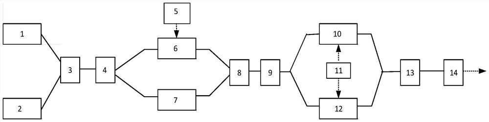
[0033] Such as figure 2 As shown, the phase encoding system based on the delay line interferometer in this embodiment includes: a first single-wavelength light source (1), a second single-wavelength light source (2), a first wavelength division multiplexer (3), a first Optical coupler (4), signal generator (5), phase modulator (6), optical delayer (7), second optical coupler (8), wave division multiplexer (9), first intensity modulation Device (10), PPG (11), second intensity modulator (12), second wavelength division multiplexer (13), photodetector (14), the specific connection relationship is as follows:

[0034] The first single-wavelength light source (1) and the second single-wavelength light source (2) are respectively connected to two ports of the first wavelength division multiplexer (3) through optical fibers; the first wavelength division multiplexer (3) is connected to the first wavelength division multiplexer (3) The optical coupler (4) is connected through an op...

Embodiment 2

[0037] This embodiment is based on the method for generating the phase encoding signal of the system of Embodiment 1, and the specific steps are as follows:

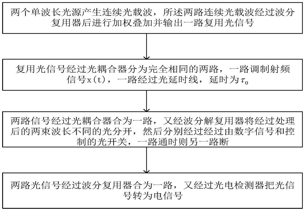
[0038] Step S1, two single-wavelength light sources generate continuous optical carriers, and the emitted light waves are: E in1 (t)=E 0 exp(jω 1 t),E in2 (t)=E 0 exp(jω 2 t), where E 0 Expressed as the electric field amplitude of the input optical carrier, ω 1 is the center frequency of the optical carrier output by LD1, ω 2 It is the center frequency of the optical carrier output by LD2. After passing through the wavelength division multiplexer, two continuous optical carriers are weighted and superimposed and output a multiplexed optical signal;

[0039] Step S2, the multiplexed optical signal is divided into two identical paths through the optical coupler, the RF signal generated by the RF signal generator is loaded on the phase modulator of the upper branch, and the lower branch is an optical delay device, an...


PUM


Abstract

The invention discloses a phase coding system and method based on a delay line interferometer, and the method comprises the following steps: S1, two single-wavelength light sources generate continuous optical carriers, the two continuous optical carriers pass through a wavelength division multiplexer, then are subjected to the weighted stacking, and output a multiplexed optical signal; s2, the multiplexing optical signal is divided into two identical paths through an optical coupler, one path is modulated into a time signal x (t) through a phase modulator, the other path passes through an optical delay line, and the delay is tau0; s3, combining the two paths of signals into one path through an optical coupler, separating the processed two beams of light with different wavelengths through a wavelength division demultiplexer, enabling the two beams of light to respectively pass through an optical switch controlled by digital signals s1 (t) and s2 (t), and enabling the other path to be switched off when one path is switched on; and S4, after the two paths of continuous optical carriers pass through a wavelength division multiplexer, weighted stacking is carried out, one path of multiplexing optical signal is output, and the optical signal is converted into an electric signal through a photoelectric detector. Devices needed by phase coding are reduced, and the system is simple and easy to implement.

Description

technical field [0001] The invention belongs to the technical field of optical communication signal processing, and in particular relates to a phase encoding method and system based on a delay line interferometer. Background technique [0002] In radar systems, in order to improve the range resolution of short pulses, phase-encoded pulse compression techniques have been extensively studied. In the traditional electrical field, the operating frequency of the phase-encoded microwave signal generated by the direct digital synthesizer (DDS) is low, and it is difficult to break through 10GHz. In the optical domain, phase-encoded microwave signal generation does not have the above-mentioned problems, and has many unique characteristics such as large operating bandwidth, high frequency, low loss, small size, and anti-electromagnetic interference. [0003] On this basis, Leaird et al. implemented a phase-encoded microwave waveform generation method based on an optical pulse shaper ...

Claims


Application Information

Patent Timeline
Patent Type & Authority Applications(China)
IPC IPC(8): H04B10/556G01S7/483
Inventor 杨淑娜朱文杰池灏杨波曾然
Owner HANGZHOU DIANZI UNIV
Why Eureka
Try Eureka