A four-terminal pair AC quantum resistance transfer bridge and method
A technology of AC resistance and four-terminal pair, which is applied in the direction of AC/DC measuring bridge, measuring electric variable, measuring device, etc., can solve the problems such as complex structure and switching of AC impedance bridge, difficult to realize, etc., to reduce mutual interference effect
- Summary
- Abstract
- Description
- Claims
- Application Information
AI Technical Summary
Problems solved by technology
Method used
Image
Examples
Embodiment 1
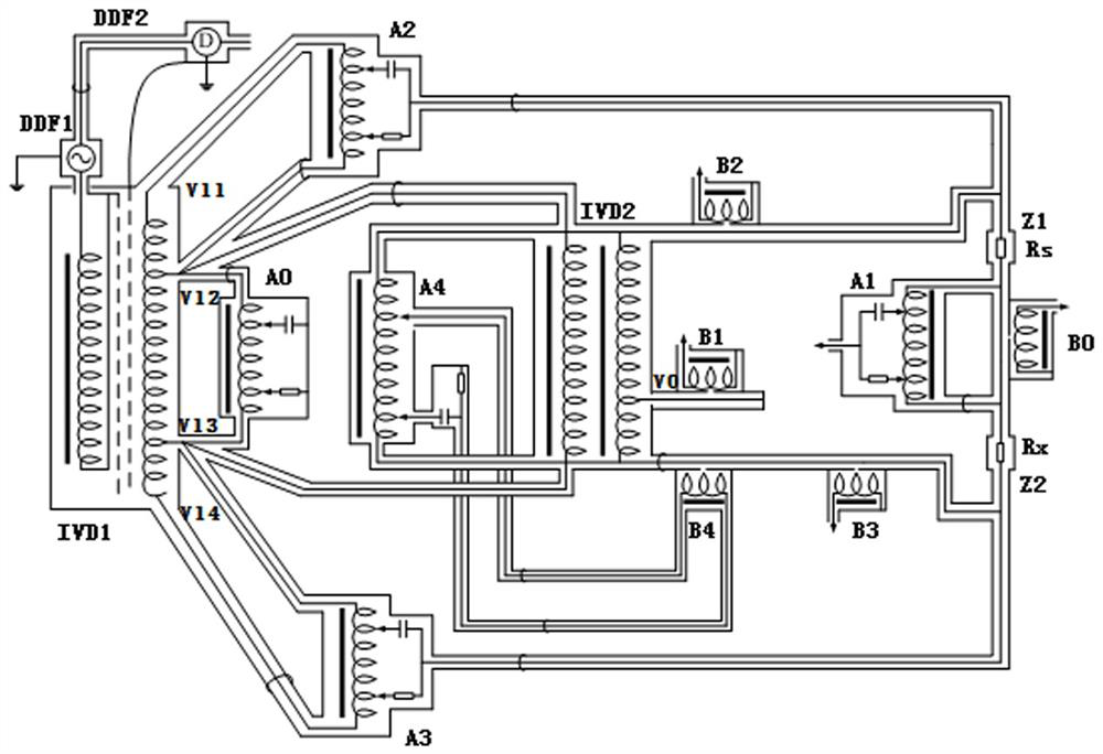
[0043] Such as image 3 As shown, a circuit diagram of a four-terminal pair AC quantum resistance transfer bridge, including an isolated induction voltage divider IVD1, a differential compensation network A4, a ratio induction voltage divider IVD2, a Wagner branch A5, and the first four-terminal pair AC resistance connection point Z1, second four-terminal pair AC resistance connection point Z2, choke coil H and zero indicator D. A standard four-terminal pair AC resistance Rs is connected to the first four-terminal pair AC resistance connection point Z1, and the standard four-terminal pair AC resistance Rs is preferably a four-terminal pair Hall quantum resistance, which can also be calibrated and can reach 10 -8 or other standard resistors with a higher uncertainty level. The second four-terminal pair AC resistance connection point Z2 is connected to the four-terminal pair AC resistance Rx to be tested.
[0044] It is known that the nominal resistance ratio of the standard f...
Embodiment 2
[0050] A method for measuring four-terminal pair AC resistance, using the above-mentioned four-terminal pair AC quantum resistance transfer bridge to measure the four-terminal pair AC resistance Rx to be measured, comprising the following steps:
[0051] Step 1. Estimate or obtain the nominal value of the four-terminal pair AC resistance Rx to be measured as 100Ω. According to the measurement requirements, select the standard four-terminal pair AC resistance Rs as the Hall quantum resistance, preferably 1KΩ, and its uncertainty level is 10 -8 Ω. Connect the second four-terminal pair AC resistance connection point Z2 of the four-terminal pair AC resistance Rx to be tested, and the standard four-terminal pair AC resistance Rs to the first four-terminal pair AC resistance connection point Z1; according to the four-terminal pair AC resistance Rx and The ratio of the standard four-terminal to the nominal value of the AC resistance Rs, the winding of the main proportional induction ...
Embodiment 3
[0061] The internal structure of the differential compensation network A4 is as Figure 5 As shown, it includes the first inductive voltage divider T1, the second inductive voltage divider T2, a set of voltage dividing resistors R (R1-R5) connected to the secondary winding L2 of the first inductive voltage divider T1, and the second A set of voltage dividing capacitor C (C1-C5), resistor R6 and compensation winding B4 connected to the secondary winding L4 of the inductive voltage divider T2, the secondary winding L2 of the first inductive voltage divider T1 and the second inductive divider The secondary winding L4 of the transformer T2 has 10 taps, and each tap has 5 connection points for the corresponding voltage-dividing resistors R (R1-R5) or voltage-dividing capacitors C (C1-C5) respectively. connect. The voltage dividing resistor R (R1-R5) and the voltage dividing capacitor C (C1-C5) respectively choose to connect or not connect the corresponding taps, which can change t...
PUM
 Abstract
Description
Claims
Application Information
 - R&D
- Intellectual Property
- Life Sciences
- Materials
- Tech Scout
- Unparalleled Data Quality
- Higher Quality Content
- 60% Fewer Hallucinations
Browse by: Latest US Patents, China's latest patents, Technical Efficacy Thesaurus, Application Domain, Technology Topic, Popular Technical Reports.
© 2025 PatSnap. All rights reserved.Legal|Privacy policy|Modern Slavery Act Transparency Statement|Sitemap|About US| Contact US: help@patsnap.com


