
System, method and equipment for controlling dilution air volume of cooling part of one-kiln two-line melting furnace

An air volume control system and a technology for a cooling section, applied in the engineering field, can solve the problems of time-consuming and laborious manual adjustment of valve switches, interference of the cooling section, and influence on the pressure and temperature control of the cooling section, etc., so as to save manual adjustment time, improve production efficiency, The effect of ensuring production safety

Active Publication Date: 2022-04-08
CHINA TRIUMPH INT ENG
View PDF5 Cites 0 Cited by
  • Summary
  • Abstract
  • Description
  • Claims
  • Application Information

AI Technical Summary

Problems solved by technology

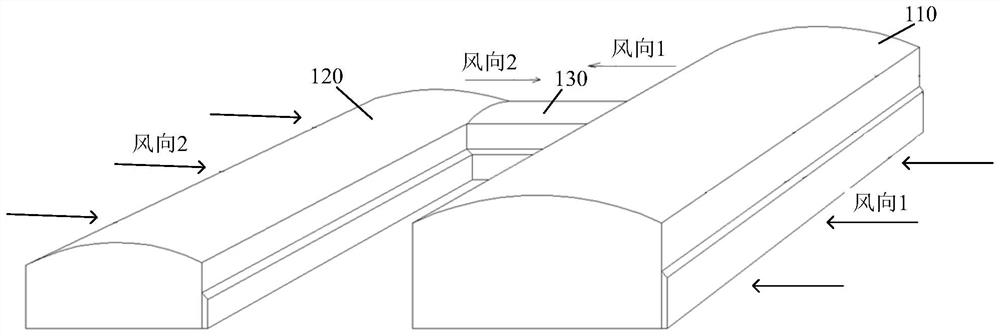
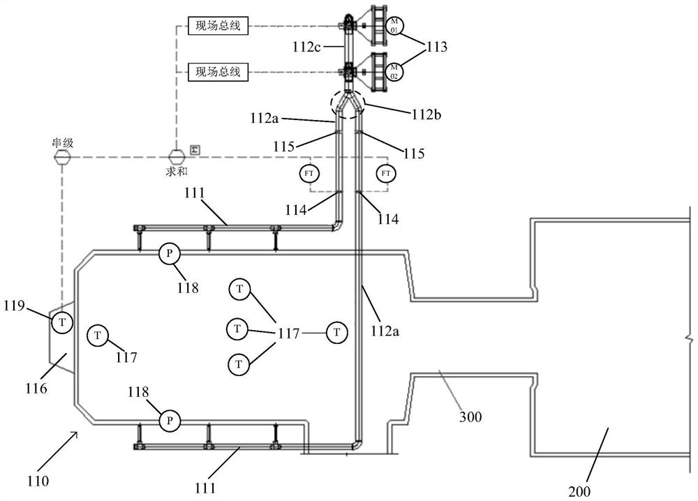
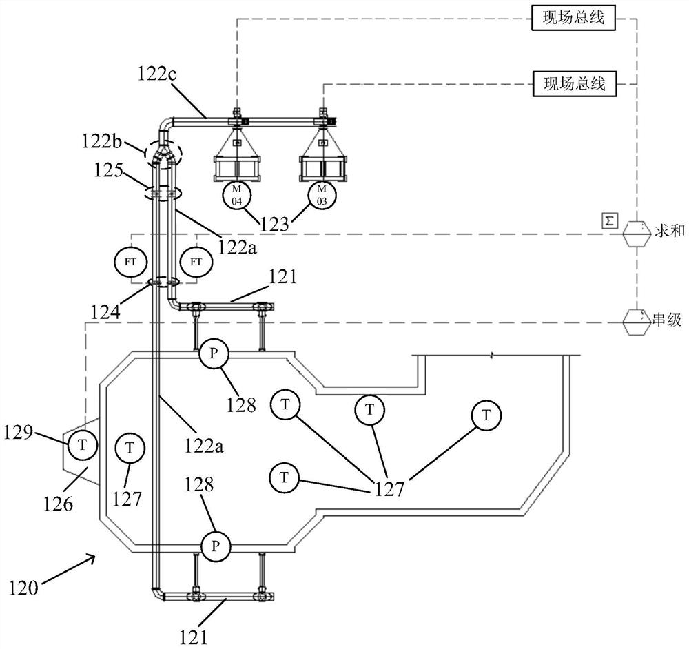
[0003] In view of the shortcomings of the prior art described above, the purpose of this application is to provide a dilution air volume control system, method and equipment for the cooling part of a furnace with two lines in a kiln, which is used to solve the time-consuming and laborious manual adjustment of valve switches in the prior art, and When the main line and the branch line are adjusted separately, the dilution wind in the two cooling parts will cause mutual interference to the respective cooling parts through the middle horizontal passage, and then affect the technical problems of the pressure and temperature control of the cooling parts.

Method used


Image

  • System, method and equipment for controlling dilution air volume of cooling part of one-kiln two-line melting furnace
  • System, method and equipment for controlling dilution air volume of cooling part of one-kiln two-line melting furnace
  • System, method and equipment for controlling dilution air volume of cooling part of one-kiln two-line melting furnace

Examples


Embodiment Construction

[0025] Embodiments of the present invention are described below through specific examples, and those skilled in the art can easily understand other advantages and effects of the present invention from the content disclosed in this specification. The present invention can also be implemented or applied through other different specific implementation modes, and various modifications or changes can be made to the details in this specification based on different viewpoints and applications without departing from the spirit of the present invention. It should be noted that, in the case of no conflict, the following embodiments and features in the embodiments can be combined with each other.

[0026] It should be noted that in the following description, reference is made to the accompanying drawings, which describe several embodiments of the present application. It is to be understood that other embodiments may be utilized, and mechanical, structural, electrical, and operational cha...


PUM


Abstract

The invention provides a one-kiln two-line melting furnace cooling part dilution air volume control system, method and equipment, and the system comprises a signal collection unit which is used for respectively obtaining the temperature of a flow liquid channel, the dilution air flow and the dilution fan operation frequency corresponding to a main line cooling part and a branch line cooling part; the cascade control unit is used for constructing a cascade control relation among the temperature of a flow liquid channel, the flow of dilution air and the running frequency of a dilution fan corresponding to the main line cooling part and the branch line cooling part respectively; and the decoupling control unit is used for eliminating the influence of cross coupling between the two cooling parts by utilizing a decoupling control algorithm according to the cascade control relation of the main line cooling part and the branch line cooling part, so that the two cooling parts independently control the temperature of the corresponding liquid flow channel by adjusting the dilution air flow. The problem of manual adjustment of a dilution air cooling system of a traditional float glass factory is avoided, and the problem of mutual influence of dilution air of two cooling parts is avoided; the manual adjustment time is saved, and the production efficiency is improved.

Description

technical field [0001] This application relates to the field of engineering technology, in particular to a dilution air volume control system, method and equipment for the cooling part of a furnace with two lines in a furnace used in the melting section of the float glass production industry. Background technique [0002] At present, in the domestic glass industry, the air system of most of the one-kiln and two-line melting furnaces in the float glass production industry mainly includes combustion-supporting fans, pool wall fans, ballast fans, etc. Since the cooling part of the float glass melting furnace is connected with the melting part through a neck, under this special structure, the cooling part cannot effectively participate in the wind circulation system, and the form of input dilution wind is often used to control the pressure on the cooling part alone. and temperature adjustments. For one kiln and two-line kiln, the main line and branch line are used to manually a...

Claims


Application Information

Patent Timeline
Patent Type & Authority Applications(China)
IPC IPC(8): C03B5/24C03B5/16
CPCY02P40/57
Inventor 刘斌宇李燕红陈智睿孙雪刘敏张卫江龙跃周祥王少波胡安峰邓析成
Owner CHINA TRIUMPH INT ENG
Learn More