
Micro-electro-mechanical system

A micro-electro-mechanical system and cantilever technology, applied in the field of micro-electro-mechanical systems, can solve problems such as low sensitivity and inoperable sensing design, and achieve the effects of normal sensitivity, increased mechanical sensitivity, and high signal-to-noise ratio

Pending Publication Date: 2022-04-08
AAC ACOUSTIC TECH (SHENZHEN) CO LTD
View PDF0 Cites 0 Cited by
  • Summary
  • Abstract
  • Description
  • Claims
  • Application Information

AI Technical Summary

Problems solved by technology

However, a high stiffness diaphragm results in low sensitivity
Conventional sensing designs will not work

Method used


Image

  • Micro-electro-mechanical system
  • Micro-electro-mechanical system
  • Micro-electro-mechanical system

Examples


Embodiment Construction

[0029] The following will clearly and completely describe the technical solutions in the embodiments of the present invention with reference to the accompanying drawings in the embodiments of the present invention. Obviously, the described embodiments are only some of the embodiments of the present invention, not all of them. Based on the embodiments of the present invention, all other embodiments obtained by persons of ordinary skill in the art without making creative efforts belong to the protection scope of the present invention.

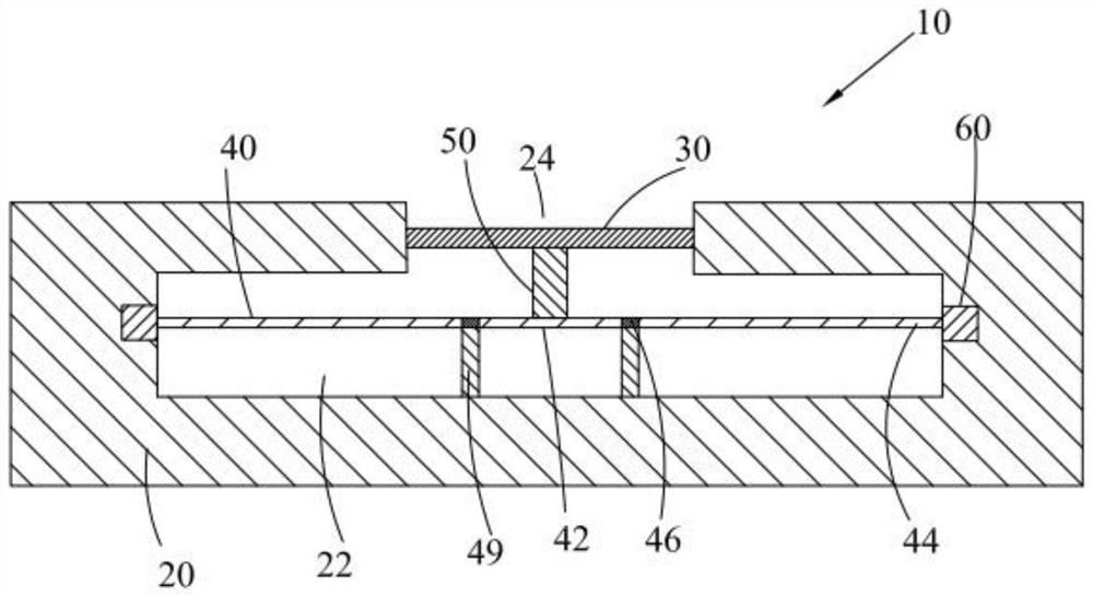
[0030] see figure 1 and figure 2 , MEMS 10 includes a housing 20 having a cavity 22 and an opening 24 communicating with the cavity 22, a diaphragm 30 installed at the opening 24, at least one cantilever 40 located in the cavity 22, and a housing 20 located at the diaphragm 30 and the plunger 50 between the cantilever 40.

[0031] In some embodiments, cavity 22 enclosed by housing 20 and diaphragm 30 is sealed from the outside atmosphere and v...


PUM


Abstract

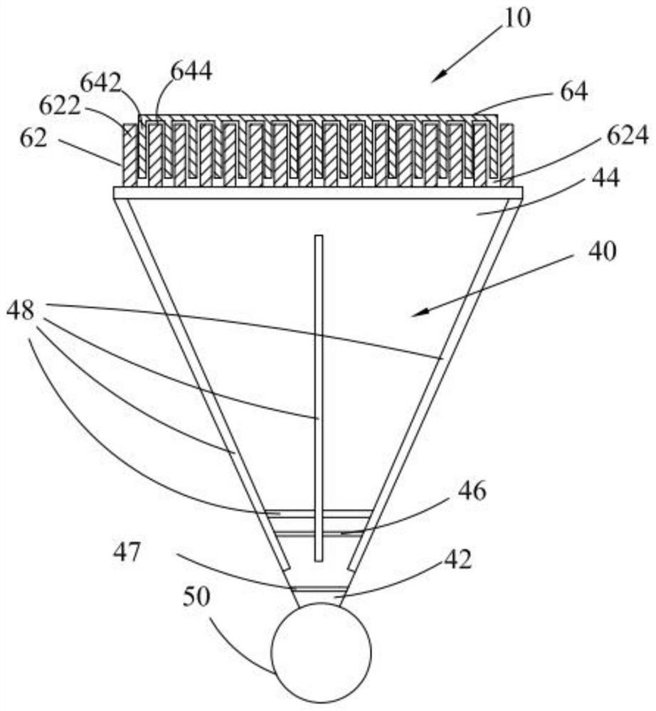
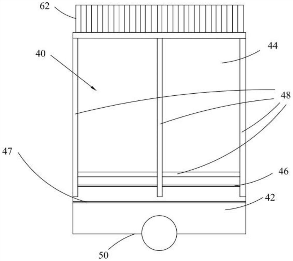
The invention provides a micro-electro-mechanical system, comprising a housing defining a cavity and an opening communicating with the cavity; the vibrating diaphragm is mounted at the opening; the at least one cantilever is located in the cavity, and the cantilever comprises a first end, a second end and a fulcrum located between the first end and the second end; the plunger is positioned between the vibrating diaphragm and the cantilever and is used for transmitting the displacement of the vibrating diaphragm to the first end of the cantilever; the sensing element is connected to the second end of the cantilever; the distance between the first end and the fulcrum is smaller than the distance between the second end and the fulcrum. The micro electro mechanical system has the advantages of being high in signal to noise ratio, small in packaging size, high in sensitivity and the like. The rigidity of the diaphragm provided by the invention is higher than the magnitude order of the diaphragm in the related technology, and mechanical collapse and large direct current deformation under 1 standard atmospheric pressure (atm) are avoided.

Description

technical field [0001] The invention relates to the field of electroacoustic transducers, in particular to a micro-electromechanical system. Background technique [0002] Conventional microelectromechanical systems (mems) microphones typically include a cavity-backed volume behind the diaphragm. The back cavity volume is the semi-sealed volume of air that undergoes compression and expansion in the presence of input sound waves. For a defined package size, cavity backing volume is necessary to allow the diaphragm to move under external pressure waves. However, back cavity volume is currently the largest source of acoustic noise, which degrades the signal-to-noise ratio (SNR) of the microphone. The smaller the back cavity volume, the higher the acoustic noise generated by the back cavity volume. Therefore, unless the package size is very large, it is very difficult to have a microphone with a signal-to-noise ratio greater than about 74dB. However, very large package sizes ...

Claims


Application Information

Patent Timeline
Patent Type & Authority Applications(China)
IPC IPC(8): H04R19/04
CPCH04R19/04H04R19/005H04R1/42H04R3/02B81B3/0021B81B2201/0257H04R2201/003B81B2203/0127B81B2203/019B81B2203/0315B81B2203/0118
Inventor 阿努普·帕特尔尤安·詹姆斯·博伊德斯科特·莱尔·嘉吉
Owner AAC ACOUSTIC TECH (SHENZHEN) CO LTD
Learn More