
Craniotomy robot and system thereof

A technology of surgical robot and mechanical arm, which is applied in the field of medical equipment, can solve the problems of internal tissue injury of the skull, doctors' lack of time to retract force, and meningeal injury, etc., to avoid medical accidents, achieve linkage effects, and ensure stable movement.

Inactive Publication Date: 2022-04-12
WENZHOU CENT HOSPITAL
View PDF0 Cites 0 Cited by
  • Summary
  • Abstract
  • Description
  • Claims
  • Application Information

AI Technical Summary

Problems solved by technology

[0003] In the existing craniotomy, after cutting the scalp, it is necessary to drill a hole on the surface of the skull with a drilling device, and then use a milling cutter to mill the skull to expose the dura mater. When the drill bit drills the surface of the skull, it is necessary to apply a certain pressure to keep the drill bit downward. However, when drilling through the skull, due to the sudden disappearance of resistance, it is easy for the doctor to be too late to retract the force, so that the drill bit continues to extend into part of the skull. It is easy to cause damage to the meninges and cause medical accidents. At the same time, after drilling through the skull, it is necessary to stop the drill in time to continue to rotate, so as to avoid damage to the internal tissues of the skull. However, there is a natural deceleration time between the power supply and the stop of the traditional drill. As a result, the drill bit will continue to rotate for a certain period of time between natural decelerations, which is likely to cause damage to the internal tissues of the skull. In summary, a craniotomy that can avoid the damage caused by the drill bit after drilling through the skull and has an emergency stop effect is needed Surgical robot and its system

Method used


Image

  • Craniotomy robot and system thereof
  • Craniotomy robot and system thereof
  • Craniotomy robot and system thereof

Examples


Embodiment Construction

[0027] The present invention will be further described in detail below with reference to the accompanying drawings and examples. The same components are indicated by the same reference numerals.

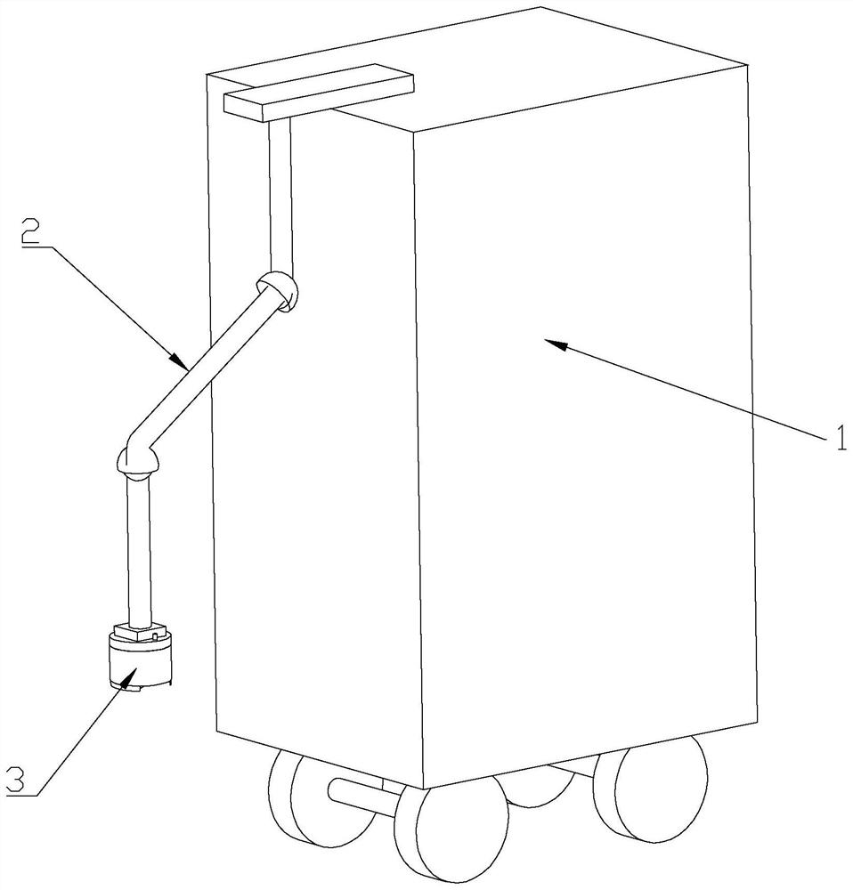
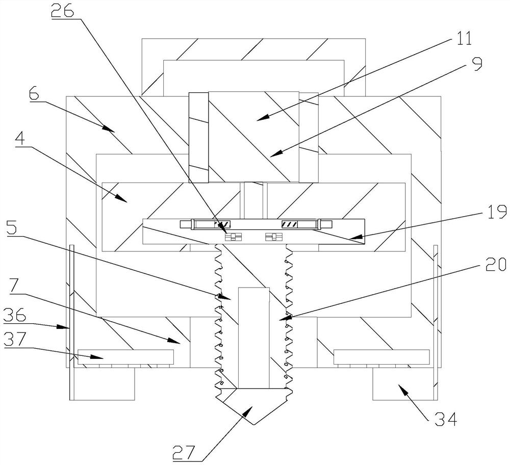
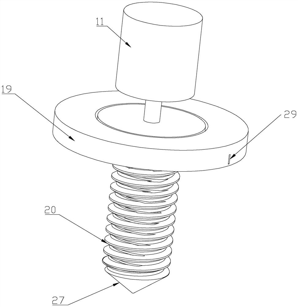
[0028] Such as Figure 1-10As shown, a craniotomy, including a frame, a moving roller having a moving roller, and a robotic arm 2 is connected to a free end connected to a craniocell. 3. In this embodiment, the robot arm 2 is a robotic arm including 5 degrees of freedom in the prior art, the craniocell member 3 including a mount 4, a drill bit 5, and a sleeve 6, the sleeve One end of the cartridge 6 is connected to the robot arm 2, and the sleeve 6 extends away from one end of the robot arm 2 to form the inner contact portion 7, the sleeve 6 to which the mounting seat 4 is used for the mounting seat 4. One end contracted, the sleeve 6 provided with a displacement assembly 8 connected to the mount 4, and the drill bit 5 is provided with a detection assembly, the detecting assembly to trans...


PUM


Abstract

The craniotomy surgical robot comprises a frame body with moving rollers, the frame body is connected with a craniotomy component through a mechanical arm, the craniotomy component comprises a mounting base, a drill bit and a sleeve, a displacement assembly is arranged in the sleeve and connected with the mounting base, and the mounting base is connected with the drill bit. The displacement assembly drives the mounting base to move in the direction away from the drill bit, an emergency stop mechanism is arranged in the drill bit, an emergency stop assembly matched with the emergency stop mechanism is arranged on the mounting base, the drill bit can be suddenly stopped through the arrangement of the emergency stop mechanism, and the pump body control unit is connected with the pump body control unit. And meanwhile, the mounting seat has a certain displacement function through the arrangement of the displacement assembly, so that the mounting seat can be displaced after the skull is drilled through, and a doctor can conveniently respond to the force.

Description

Technical field [0001] The present invention relates to the technical field of medical devices, and more specifically is a craniotomy, a system, and a system. Background technique [0002] Craniotic surgery, that is, the patient's skull is opened by mechanical equipment, thereby making some unconventional treatment. [0003] In the existing craniotomy, after cutting the scalp, it is necessary to drilled through the drilling equipment, and then the skull is milked by the milling cutter, thereby exposing the cardium, and in the existing craniutable equipment, in the doctor's operation When the drill bit drills the surface of the skull, it is necessary to apply a certain pressure to keep the drill bit downward, but when drilling the skull, because the resistance suddenly disappears, it is easy to cause the doctor to be easy to make up, so that the drill should continue to enter some skulls, thus It is easy to cause damage to the meningum, causing medical accidents, and after drillin...

Claims


Application Information

Patent Timeline
Patent Type & Authority Applications(China)
IPC IPC(8): A61B17/16
Inventor 孙军蔡建勇林孝瑜叶良智林群巴华君戴君侠
Owner WENZHOU CENT HOSPITAL
Learn More