Paint spraying device for new energy automobile parts
A technology for new energy vehicles and accessories, which is applied in spraying devices, spray booths, and devices for coating liquid on surfaces, etc. It can solve the problems that affect the handling of parts by the staff, the adhesion of paint by the staff, and the incomplete spraying of parts, etc., to achieve Improve the hardness, reduce the workload, and prevent the effect of not being easy to spray
- Summary
- Abstract
- Description
- Claims
- Application Information
AI Technical Summary
Problems solved by technology
Method used
Image
Examples
Embodiment 1
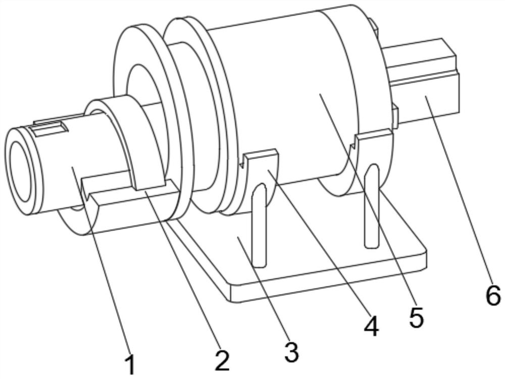
[0035] see Figure 1-2 , the present invention provides a technical solution: a new energy auto parts painting device, including a fixed bottom plate 3, both sides of the top of the fixed bottom plate 3 are fixedly connected with supporting feet 4, and the top of the supporting feet 4 is fixedly connected with a painting device 5, The right outer wall of the paint spraying device 5 is provided with a power body 6, the output end of the power body 6 runs through the paint spraying device 5 and extends to the inside of the paint spraying device 5, and the bottom of the left side outer wall of the paint spraying device 5 is fixedly connected with a fixed frame 2, and the fixed frame 2 Feeder 1 is movably connected to both sides of the inner chamber bottom.
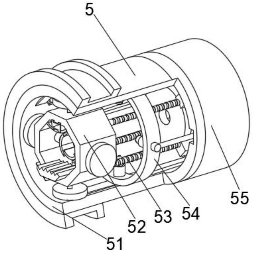
[0036] Wherein, the paint spraying device 5 comprises a paint spraying tube 51, a paint spraying ring 54 is arranged in the middle part of both sides of the paint spraying tube 51, and a protective mechanism 55 is fixedly con...
Embodiment 2
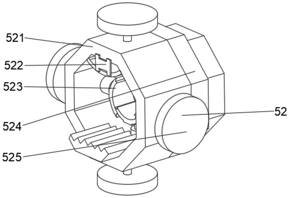
[0039] see Figure 1-4 , on the basis of Embodiment 1, the present invention provides a technical solution: Component 1 of the connecting mechanism 52 includes a connecting positioning block 521, and the middle parts of the outer walls of both sides of the connecting positioning block 521 are fixedly connected with a stabilizing block 525, and the connecting positioning block 521 Both sides of the back side are fixedly connected with extension body 524, and the middle position of the inner cavity top connected with positioning block 521 is fixedly connected with blocking frame 522, and the middle part of the inner wall of both sides connected with positioning block 521 is provided with fastening body 523.
[0040] Among them, the first component of the protective mechanism 55 includes a protective shell 551, the inner walls of both sides of the protective shell 551 are provided with a rotating disk 552, and the front sides of the rotating disk 552 are fixedly connected with tel...
Embodiment 3
[0043] see Figure 1-6 , on the basis of Embodiment 1 and Embodiment 2, the present invention provides a technical solution: component 2 of the connection mechanism 52 includes an extrusion ring d2, and the outer surface of the extrusion ring d2 is fixedly connected with a fixed guide post d1, and the extrusion The middle part of the inner wall on both sides of the ring d2 is provided with an elastic spacer d5, and the side of the elastic spacer d5 away from the extrusion ring d2 is fixedly connected with an isolation net d4, and the side of the isolation net d4 far away from the elastic spacer d5 is fixedly connected with a connection The frame d3 and the side of the elastic spacer d5 away from the isolation screen d4 run through the extrusion ring d2.
[0044] Wherein, the second component of the protective mechanism 55 includes a collector t2, the outer wall of the right side of the collector t2 is fixedly connected to the capsule body t1, and the side of the collector t2 a...
PUM
 Abstract
Description
Claims
Application Information
 - R&D
- Intellectual Property
- Life Sciences
- Materials
- Tech Scout
- Unparalleled Data Quality
- Higher Quality Content
- 60% Fewer Hallucinations
Browse by: Latest US Patents, China's latest patents, Technical Efficacy Thesaurus, Application Domain, Technology Topic, Popular Technical Reports.
© 2025 PatSnap. All rights reserved.Legal|Privacy policy|Modern Slavery Act Transparency Statement|Sitemap|About US| Contact US: help@patsnap.com


