
Novel main shaft broach mechanism with integrated pull claw

An integrated, claw-pulling technology, applied in the field of machine tool parts, can solve the problems of easy accumulation of water in the taper hole of the spindle, failure to achieve cooling effect, easy rust, etc., and achieve protection stability, small failure rate, and good dynamic balance. Effect

Pending Publication Date: 2022-04-12
清远市天一数控设备有限公司
View PDF0 Cites 0 Cited by
  • Summary
  • Abstract
  • Description
  • Claims
  • Application Information

AI Technical Summary

Problems solved by technology

The main shaft of the horizontal machining center is set horizontally. When the broaching mechanism is in the same horizontal state, water is easy to accumulate in the taper hole of the main shaft, and the ring spring is easy to rust when the ring spring is slightly longer. (The fatigue life of the stainless steel spring is not as good as that of the spring steel). The spring elastic tie makes the front end of the claw claws open. When the ring spring fails or the elastic force is small, the two upper pieces of the claw claws that are opened will sag under the action of their own weight, and the handle will be stuck. Pulling the nail, when the automatic tool changer manipulator pulls out the knife, the knife may fall off, or the knife may be stuck and cannot be pulled out;
[0004] For the cutting process of horizontal machining centers, water spray pipes are generally installed on the front of the spindle to spray water for cooling, but it still cannot achieve a strong cooling effect and greatly improve the cutting efficiency;

Method used


Image

  • Novel main shaft broach mechanism with integrated pull claw
  • Novel main shaft broach mechanism with integrated pull claw
  • Novel main shaft broach mechanism with integrated pull claw

Examples


Embodiment Construction

[0027] The present invention will be further described below with reference to the accompanying drawings.

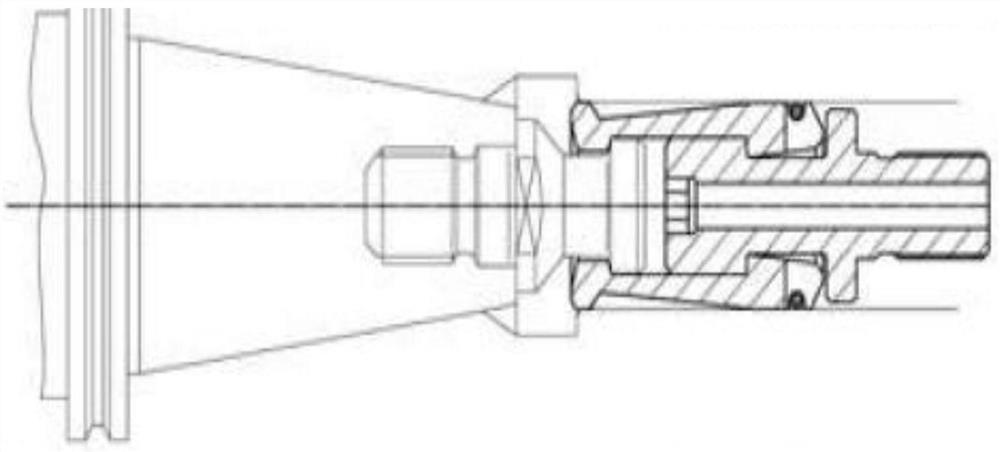
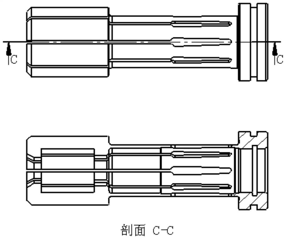
[0028] In particular, in the specific implementation, in order to solve the above problem, the claw of the new type of pull-in mechanism is an integrated claw. The outer shape is as shown in Fig. -2, and the top of this new type can be divided into a front middle and third part, in which the front The two parts are divided into eight petals, and the latter portion is the entire outer diameter of the ring, the outer diameter of the latter portion is larger than the outer diameter of the first mid-end portion is divided into the entire portion, the outer portion of the intermediate portion is smaller than the front and rear parts, the inner diameter shape: overall Through holes, the integrated tip front end portion is a groove, between the intermediate portion and the front end portion;

[0029]The air source channel of the present invention is, the rotary coupling mounting ro...


PUM


Abstract

The invention discloses a novel high-speed spindle broach mechanism with an integrated pull claw. The device structurally comprises a main shaft core, a BT cutter handle, a blind rivet, an integrated pull claw, a water spraying ejector rod, a trapezoidal groove pull head, a broach rod, a water spraying ejector rod threaded connection sleeve, a pushing spring, a disc spring front pad, a disc spring set, a disc spring middle gasket, a middle water guide rod, a shaft core rear cover, a middle connection ring, a rear connection pressing ring, a rotary connector installation rod, a bearing supporting ring, a distance ring and a rear water guide rod. The novel main shaft broach mechanism is designed for a horizontal machining center main shaft of a high-end numerical control machine tool, and the integrated pull claw is adopted, so that the rotating speed of the main shaft can be effectively increased due to good rotating dynamic balance; the stability of tool loosening and pulling actions can effectively assist in improving the stability of automatic tool changing of the horizontal machining center, and by combining a new machining technology of high-pressure cutting water spraying, the machining efficiency can be effectively improved, the cutting performance can be improved, the service life of a tool can be prolonged, tool loss can be reduced, and the machining cost can be saved.

Description

Technical field [0001] The present invention relates to the field of machine tool components, and specifically, an new high-speed spindle mechanism applied to a horizontal machined heart shaft, a claw is an integrated, and a spindle center can spray water, the front end of the spindle. Background technique [0002] Horizontal machining center, CNC boring machine, opposite machining center, no matter how much technical barriers are highly difficult, complexity, most of the domestic CNC machine tool manufacturers are concentrated in the production of medium and low-end machining centers, while production horizontal processing The center manufacturer is not numbered, and the high-precision horizontal machining center can be less, but there are many superiority of the vertical machining center of the horizontal machining center, first of all the workbench is open, facilitating the installation of the workpiece, can be installed Large-scale rotating workbench can be installed to impro...

Claims


Application Information

Patent Timeline
Patent Type & Authority Applications(China)
IPC IPC(8): B23Q3/155B23Q11/00B23Q11/10
Inventor 陶一帆陶天健陶跃明
Owner 清远市天一数控设备有限公司
Learn More