Visual servo feeding special-shaped spiral curved surface screw abrasive belt polishing device and method

A helical curved surface and visual servo technology, which is applied in the direction of abrasive belt grinder, grinding/polishing equipment, workpiece feed movement control, etc., can solve the problem that it is difficult to adapt to the variable-lead special-shaped screw, which affects the polishing path and CNC machining accuracy, Affect production efficiency and economic benefits and other issues, to achieve the effect of enhancing processing flexibility and continuous production capacity, improving polishing accuracy and processing quality, and improving process design efficiency

Active Publication Date: 2022-04-12
YANGZHOU UNIV
View PDF8 Cites 1 Cited by
  • Summary
  • Abstract
  • Description
  • Claims
  • Application Information

AI Technical Summary

Problems solved by technology

However, the existing methods can only realize the automation of the polishing process. In the early stage, it is still necessary to manually measure the geometry of the workpiece surface to determine the thread specification, plan the polishing path, and compile the NC program.
The direct measurement of the spiral surface by the technician will introduce a large measurement geometric error, which is difficult to adapt to the special shaped screw with variable lead and variable thread lead angle, which will affect the polishing path and CNC machining accuracy
The measurement, path planning and NC programming of different types of special-shaped screws not only consume a lot of time, but also put forward high requirements for the experience and technology of technicians, seriously affecting production efficiency and economic benefits
Therefore, the current CNC abrasive belt polishing method has the disadvantages of poor production flexibility, low processing accuracy, and low production efficiency.

Method used


Image

  • Visual servo feeding special-shaped spiral curved surface screw abrasive belt polishing device and method
  • Visual servo feeding special-shaped spiral curved surface screw abrasive belt polishing device and method
  • Visual servo feeding special-shaped spiral curved surface screw abrasive belt polishing device and method

Examples


Embodiment Construction

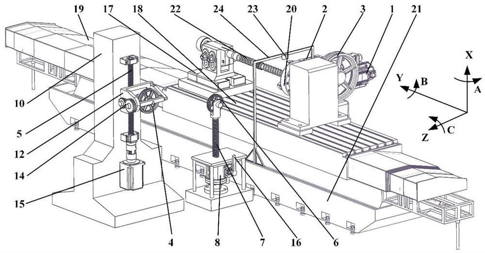
[0033] Such as figure 1 The shown a visual servo feeding special-shaped spiral curved surface screw abrasive belt polishing device includes a bed 21, and also includes an abrasive belt drive mechanism, a screw feed mechanism, a binocular vision acquisition mechanism and a data processing unit; the abrasive belt drive mechanism is fixed Installed on both sides of the bed 21, the screw feed mechanism is installed on the bed 21, the binocular vision acquisition mechanism is fixed on the bed 21 through the support mechanism, and the collected data is transmitted to the data processing unit; the abrasive belt drive mechanism includes A driving wheel mechanism, a driven wheel mechanism and a tensioning wheel mechanism; the driving wheel mechanism, the driven wheel mechanism and the tensioning wheel mechanism are sequentially connected through an abrasive belt.

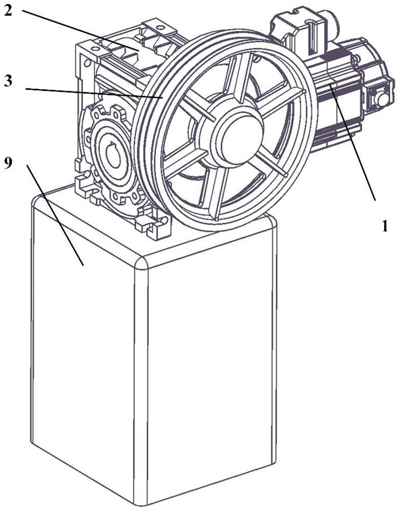
[0034] Such as figure 2 As shown, the driving wheel mechanism includes a driving motor 1, a reducer 2 and a driving whee...


PUM


Abstract

The invention discloses a visual servo feeding special-shaped spiral curved surface screw abrasive belt polishing device which comprises a lathe bed and further comprises an abrasive belt driving mechanism, a screw feeding mechanism, a binocular vision collecting mechanism and a data processing unit. The invention discloses a visual servo feeding abrasive belt polishing method for a special-shaped spiral curved surface screw. The method comprises the steps that (1) a whole machine is installed, and a camera is calibrated; 2) acquiring three-dimensional information; 3) calibrating a workpiece coordinate system; 4) thread segment segmentation; the special-shaped screw rod polishing machining method has the advantages that good feasibility is achieved, the special-shaped screw rod polishing machining method can meet the market requirements of small-batch production, automation, high precision and high efficiency of current special-shaped screw rod polishing machining, and the competitiveness of enterprises is effectively improved in the aspects of production flexibility, machining efficiency, environmental protection and economic benefits.

Description

technical field [0001] The invention relates to the technical field of mechanical processing, in particular to a visual servo feeding special-shaped spiral curved surface screw abrasive belt polishing device and method. Background technique [0002] Special-shaped helical surface screw (hereinafter referred to as special-shaped screw) is one of the core parts of complex mechanical equipment such as injection molding machines, compressors, and screw pumps. Compared with ordinary screws, the most important feature of special-shaped screws is its complex geometric structure, which often contains multiple thread segments with different root diameters, leads, and helix angles. The market demand for special-shaped screws has the characteristics of high precision and small batches: special-shaped screws are often used in the core power components of key mechanical equipment, and require high surface accuracy; different mechanical equipment requires different types of special-shaped...

Claims


Application Information

Patent Timeline
Patent Type & Authority Applications(China)
IPC IPC(8): B24B1/00B24B21/00B24B21/18B24B21/20B24B41/02B24B41/06B24B49/00
Inventor 何词孙进张智干
Owner YANGZHOU UNIV
Why Eureka
Try Eureka