
Fuel gas generator

A gas generator and fuel technology, applied in jet propulsion devices, machines/engines, rocket engine devices, etc., can solve problems such as burnout, troublesome disassembly and assembly, and overheating of injectors

Pending Publication Date: 2022-04-12
CENT SOUTH UNIV
View PDF0 Cites 0 Cited by
  • Summary
  • Abstract
  • Description
  • Claims
  • Application Information

AI Technical Summary

Problems solved by technology

[0005] However, the design and processing of existing gas generators are based on disposable liquid rocket engine combustion chambers, without consideration of modularity, interchangeability and maintainability. The components are mainly connected by welding, which is troublesome to disassemble. The whole will lose its basic functions when it fails, and it is not suitable for testing the functions of different structures during ground tests, and the cost is high
[0006] It is extremely difficult to reliably ignite the gas generator using dual low-temperature propellants. The igniter of the existing gas generator is installed on the head, and the ignition high-temperature gas is introduced into the combustion chamber through a long thin tube, and flows through the low-temperature fuel chamber of the head. Longer, the loss of gas temperature is greater, often causing the gas generator to fail to ignite
[0007] The existing gas generator scheme adopts radiation cooling and regenerative cooling, and the injector does not have any thermal protection measures. It can only provide thermal protection for the body of the combustion chamber, which may easily cause the injector to overheat or even burn out, which limits the number of times the gas generator can be used. , which also limits the temperature of the gas produced by the gas generator, which cannot exceed 1000°C

Method used


Image

  • Fuel gas generator
  • Fuel gas generator
  • Fuel gas generator

Examples


Embodiment Construction

[0037] The core of the invention is to provide a gas generator, which can improve the success rate of ignition.

[0038] The following will clearly and completely describe the technical solutions in the embodiments of the present invention with reference to the accompanying drawings in the embodiments of the present invention. Obviously, the described embodiments are only some, not all, embodiments of the present invention. Based on the embodiments of the present invention, all other embodiments obtained by persons of ordinary skill in the art without making creative efforts belong to the protection scope of the present invention.

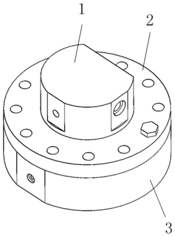
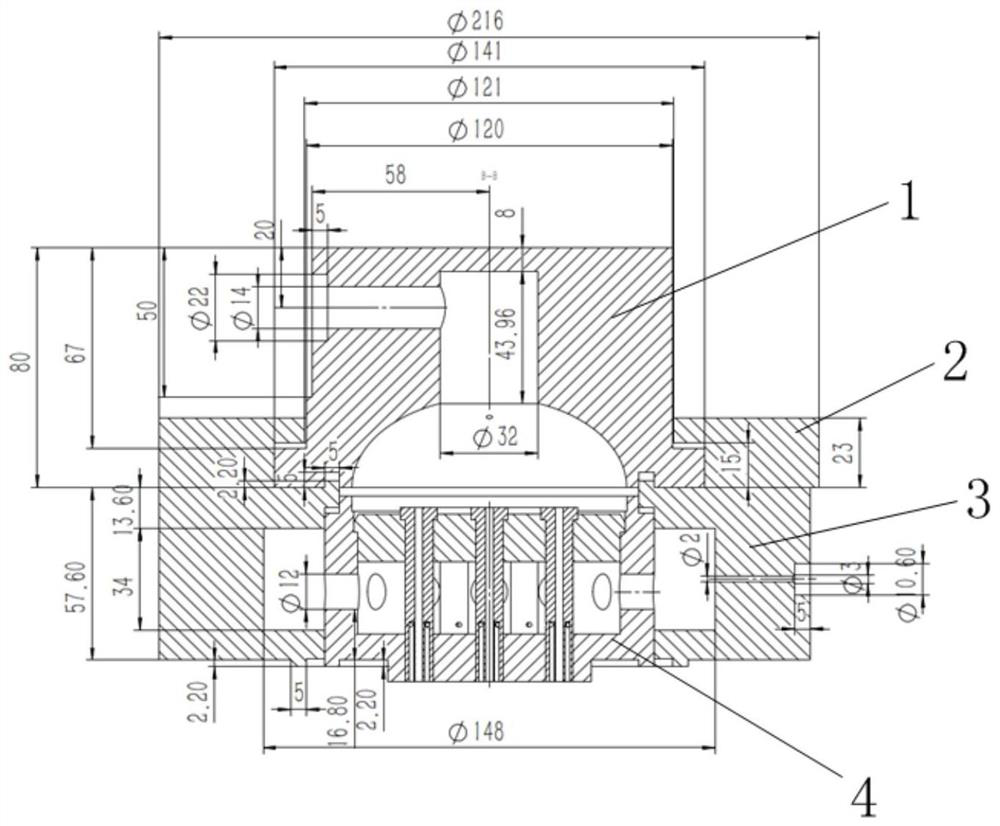
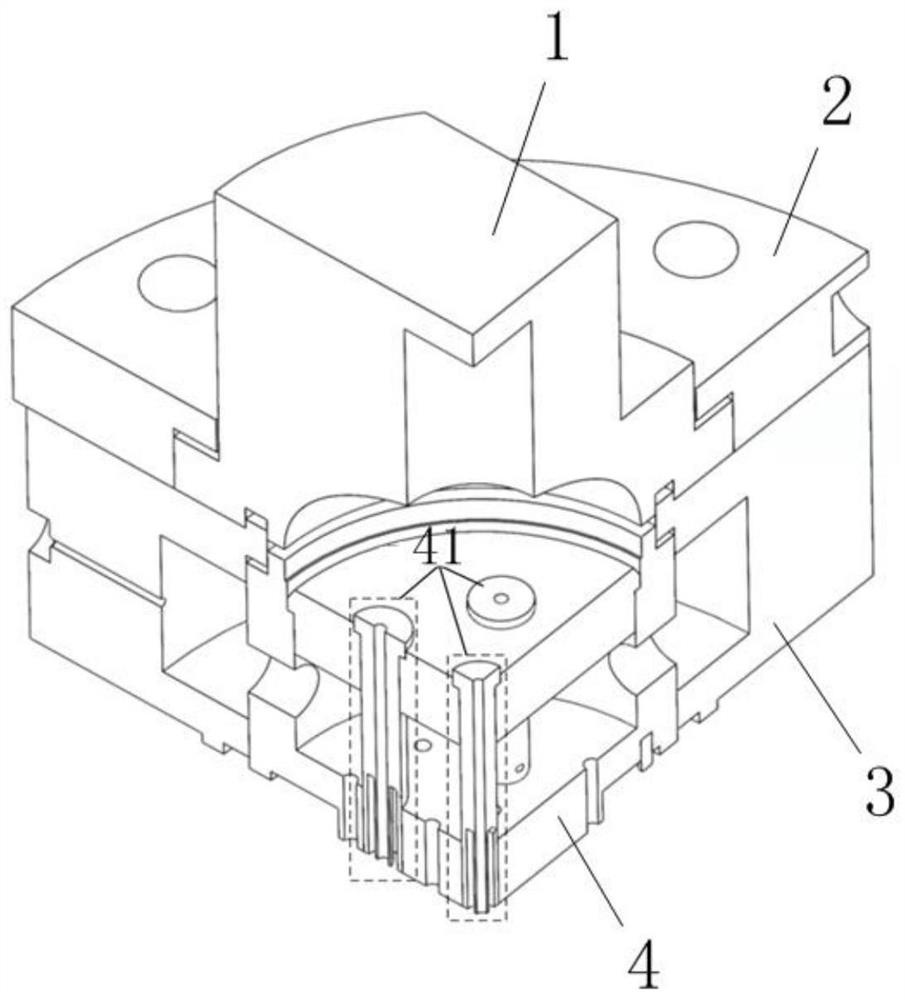
[0039] Please refer to Figure 1 to Figure 7 , figure 1 It is a schematic structural view of the gas generator head provided by a specific embodiment of the present invention; figure 2 is a sectional view of the gas generator head; image 3 is the structural diagram of the head of the gas generator; Figure 4 is a schematic diagram of the stru...


PUM


Abstract

The invention discloses a fuel gas generator which comprises a combustion chamber head, a combustion chamber body connected with the combustion chamber head and a spark plug arranged on a combustion chamber, and the combustion chamber head comprises an injector, a fuel liquid collecting ring arranged on the periphery of the injector and a liquid oxygen liquid collecting cavity arranged on the injector. A liquid oxygen inlet pipe joint is arranged on the liquid oxygen collecting cavity, a fuel inlet pipe joint is arranged on the fuel liquid collecting ring, the injector comprises a plurality of coaxial injection units, each coaxial injection unit comprises a central liquid oxygen flow channel and an outer ring fuel flow channel, the central liquid oxygen flow channel is communicated with the liquid oxygen collecting cavity, the outer ring fuel flow channel is communicated with the fuel liquid collecting ring, and the fuel inlet pipe joint is communicated with the fuel liquid collecting ring. And a tail end liquid oxygen nozzle of the central liquid oxygen flow channel and a tail end fuel nozzle of the outer ring fuel flow channel are communicated with the combustion chamber body part. The mixing ratio of the central area of the fuel gas generator is close to the equivalent mixing ratio, combustion can be promoted, and the ignition success rate is increased; the boundary mixing ratio is far away from the equivalent mixing ratio, the fuel gas temperature is limited not to be too high, and the working time can be prolonged.

Description

technical field [0001] The invention relates to the field of gas generators, in particular to a gas generator. Background technique [0002] Liquid rocket engine (Liquid Rocket Engine, LRE) has high technical maturity and inheritance, low development risk and low cost, and is the preferred propulsion solution for reusable rockets. Among them, liquid oxygen methane engine has the best reusability. Aerospace research agencies began to shift their focus to liquid oxygen methane engines. Methane is abundant in nature and is the main component of natural gas, combustible ice, etc., and its price is much lower than kerosene and liquid hydrogen. As a rocket motor propellant, methane performs well. Methane propellant is non-toxic and non-polluting. It is a green propellant and is easy to use and maintain. As the hydrocarbon fuel with the lightest molar mass, methane has excellent combustion performance, low carbon deposition, no coking during cooling, and good material compatibil...

Claims


Application Information

Patent Timeline
IPC IPC(8): F02K9/62F02K9/60F02K9/95F02K9/52F02K9/64
Inventor 宋佳文刘俊罗世彬许德泉冯彦斌
Owner CENT SOUTH UNIV
Learn More