Nondestructive testing and evaluation method for strong laser damage characteristics of optical element
A technology for optical components and non-destructive testing, applied in neural learning methods, optical testing of flaws/defects, material analysis through optical means, etc., can solve the problems of long laser damage testing cycle, unrepeatable testing, and high testing costs Evaluate device reliability, improve system reliability and availability, and improve the effect of processing technology
- Summary
- Abstract
- Description
- Claims
- Application Information
AI Technical Summary
Problems solved by technology
Method used
Image
Examples
Embodiment 1
[0067] Embodiment 1 Acquisition of non-destructive testing parameter data of prior optical components
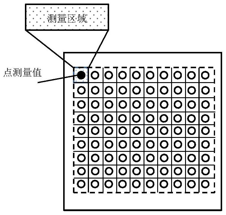
[0068] like figure 2 As shown, using spectrophotometer, absorption coefficient tester, stimulated fluorescence tester, roughness meter, refractive index tester, surface curvature tester according to figure 2 In the manner shown, the transmittance, absorption, stimulated fluorescence, roughness, refractive index, surface curvature distribution, etc. are obtained by point-by-point scanning. During the point-by-point scanning process, the coordinate position of the scanning area relative to the optical element should be recorded and the measured value should be entered into the corresponding position. like figure 2 As shown, when the measurement area is large and the measurement value in the measurement area is relatively stable, all the values of the parameter in the area can be replaced by the measurement value, such as figure 2 In , the black dots represent the meas...
Embodiment 2
[0074] Embodiment 2 Acquisition of prior optical element damage detection parameter data
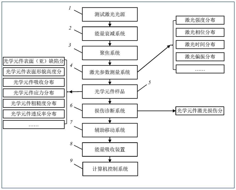
[0075] The principle diagram of the optical element lossy test data acquisition process in the present invention refers to the appended image 3 , the destructive test data testing system includes: testing laser light source 1, energy attenuation system 2, focusing system 3, laser parameter measurement system 4, optical component sample 5, damage diagnosis system 6, auxiliary moving system 7, energy absorption device 8, computer control system9. The auxiliary moving system adjusts the position of the optical element sample 5 . In addition to obtaining the laser parameter distribution data, the laser parameter measurement system 4 also has the function of calibrating the positional relationship of the laser beam and the coordinate system of the optical element, calibrating the characteristic position of the laser beam through the light, and calculating the relationship between the laser b...
Embodiment 3
[0089] Embodiment 3 Convolutional Neural Network Calculation LIDRM
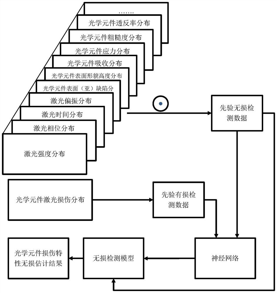
[0090] On the basis of Embodiment 1 and Embodiment 2, the relationship model LIDRM (Laser Induced Damage Relationship Model) between the prior nondestructive inspection data and the prior destructive inspection data is obtained by analyzing the prior optical element surface inspection data. For details, please refer to the attached Figure 4 .
[0091] The convolutional network is randomly generated, and the convolutional neural network includes at least an input layer, a hidden layer, and an output layer. In this embodiment, a multi-layer neural network is used.
[0092] Randomly select n original data matrices Data_n(u, v) in the data set, and add them to the random bias matrix B after convolving with multiple randomly generated convolution kernels W to generate multiple FeatureMaps, which are activated by activation functions (such as , sigmaio function or Relu function) into the next network layer. Th...
PUM
 Abstract
Description
Claims
Application Information
 - R&D
- Intellectual Property
- Life Sciences
- Materials
- Tech Scout
- Unparalleled Data Quality
- Higher Quality Content
- 60% Fewer Hallucinations
Browse by: Latest US Patents, China's latest patents, Technical Efficacy Thesaurus, Application Domain, Technology Topic, Popular Technical Reports.
© 2025 PatSnap. All rights reserved.Legal|Privacy policy|Modern Slavery Act Transparency Statement|Sitemap|About US| Contact US: help@patsnap.com


