Intelligent monitoring acquisition instrument for vibrating wire sensor
A vibrating wire sensor and intelligent monitoring technology, which is applied in the direction of instruments, simulators, general control systems, etc., can solve the problems of cost increase, complex structure, data loss, etc., and achieve the effect of good waterproof performance, simple equipment operation, and easy maintenance
- Summary
- Abstract
- Description
- Claims
- Application Information
AI Technical Summary
Problems solved by technology
Method used
Image

Examples
Embodiment 1
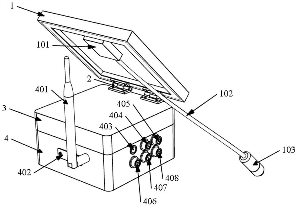
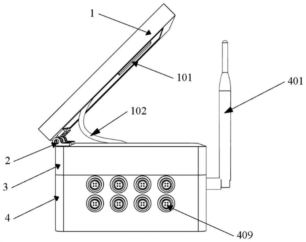
[0035] An intelligent monitoring and collecting instrument for vibrating wire sensors, its appearance, see the attached Figure 1-2 , including a box body and a polycrystalline silicon solar panel 1 connected to the box body.
[0036] The box includes an upper shell 3 and a lower shell 4, the upper shell 3 and the lower shell 4 are fixedly connected up and down to form a square box, and the polycrystalline silicon solar panel 1 is connected to the upper shell through a damping hinge 2 body 3.
[0037] A junction box 101 is provided on the back of the polycrystalline silicon solar panel 1 , and the junction box 101 is connected to a plug 103 through an external wire.
[0038] A power switch 403, a solar charging interface 404, a charger charging interface 405, an RS485 communication interface 406, a program download interface 407, and a backup interface 408 are provided on the first side of the lower housing 4; There are 8 vibrating wire sensor interfaces 409 ; an antenna 401...
Embodiment 2
[0041] On the basis of Embodiment 1, this embodiment combines the attached Figure 3-6 The internal control system of the intelligent monitoring and collecting instrument used for vibrating wire sensors is introduced.
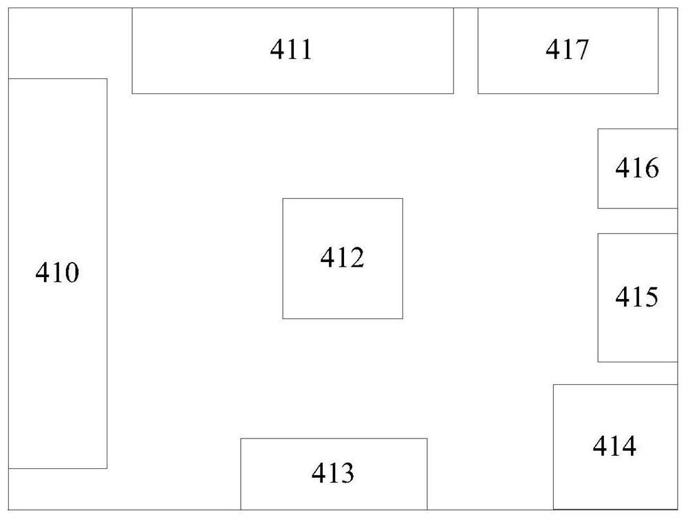
[0042] See attached image 3 , the cabinet inside of described intelligent monitoring collection is provided with control system, and this control system comprises: 8 relays 410 (the same as the quantity of vibrating wire sensor interface 409), a signal acquisition module 411, MCU microprocessor unit 412, 4G Communication module 413, power management unit 414, program download module 415, EEPROM storage module 416, RS485 communication module 417, storage battery and solar charge controller.
[0043] The input end of the solar charge controller is connected to the solar charge interface 404, and the output end of the solar charge controller is connected to the storage battery. When the plug 103 of the polysilicon solar panel 1 is inserted into the solar charge ...
Embodiment 3
[0049] Further, when working, the MCU microprocessor unit 412 further analyzes the digital signal, and uploads the data to the cloud server via the 4G communication module 413 .
[0050] Furthermore, if the engineering application is carried out in an area without network signal, the MCU microprocessor unit 412 can directly store the digital signal in the EEPROM storage module 416, and upload it to the cloud server after being connected to the network signal.
[0051] Further, when the RS485 communication module 417 is connected to the master station through the RS485 communication interface 406, the data can also be transmitted to the master station through the RS485 communication module.
[0052] Furthermore, when the acquisition instrument is not collecting vibrating wire signals, the power supply of the signal acquisition module 411 and the 4G communication module 413 are both cut off, and the acquisition instrument is in a dormant state, thereby greatly reducing power cons...
PUM
 Abstract
Description
Claims
Application Information
 - R&D Engineer
- R&D Manager
- IP Professional
- Industry Leading Data Capabilities
- Powerful AI technology
- Patent DNA Extraction
Browse by: Latest US Patents, China's latest patents, Technical Efficacy Thesaurus, Application Domain, Technology Topic.
© 2024 PatSnap. All rights reserved.Legal|Privacy policy|Modern Slavery Act Transparency Statement|Sitemap