Broadband circularly polarized patch antenna

A patch antenna and circular polarization technology, which is applied in the directions of antenna grounding device, antenna grounding switch structure connection, radiation element structure, etc., can solve the problems affecting the antenna radiation pattern, expand broadband characteristics, reduce parasitic radiation, Ease of processing and assembly

Active Publication Date: 2022-04-12
SYNERGY INNOVATION INST OF GDUT HEYUAN
View PDF5 Cites 0 Cited by
  • Summary
  • Abstract
  • Description
  • Claims
  • Application Information

AI Technical Summary

Problems solved by technology

However, the coupling structure in the feed circuit is prone to spurious radiation, affecting the radiation pattern of the antenna

Method used


Image

  • Broadband circularly polarized patch antenna
  • Broadband circularly polarized patch antenna
  • Broadband circularly polarized patch antenna

Examples


Embodiment Construction

[0028] specific implementation plan

[0029] Below in conjunction with accompanying drawing, technical scheme of the present invention is described further:

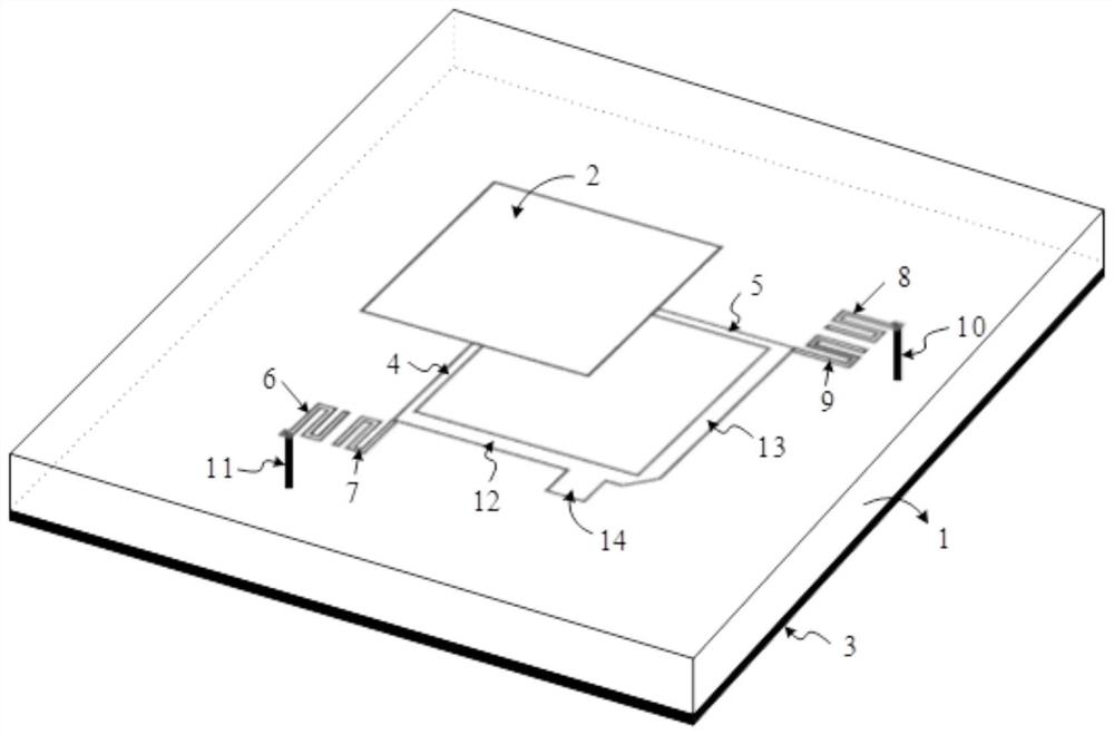
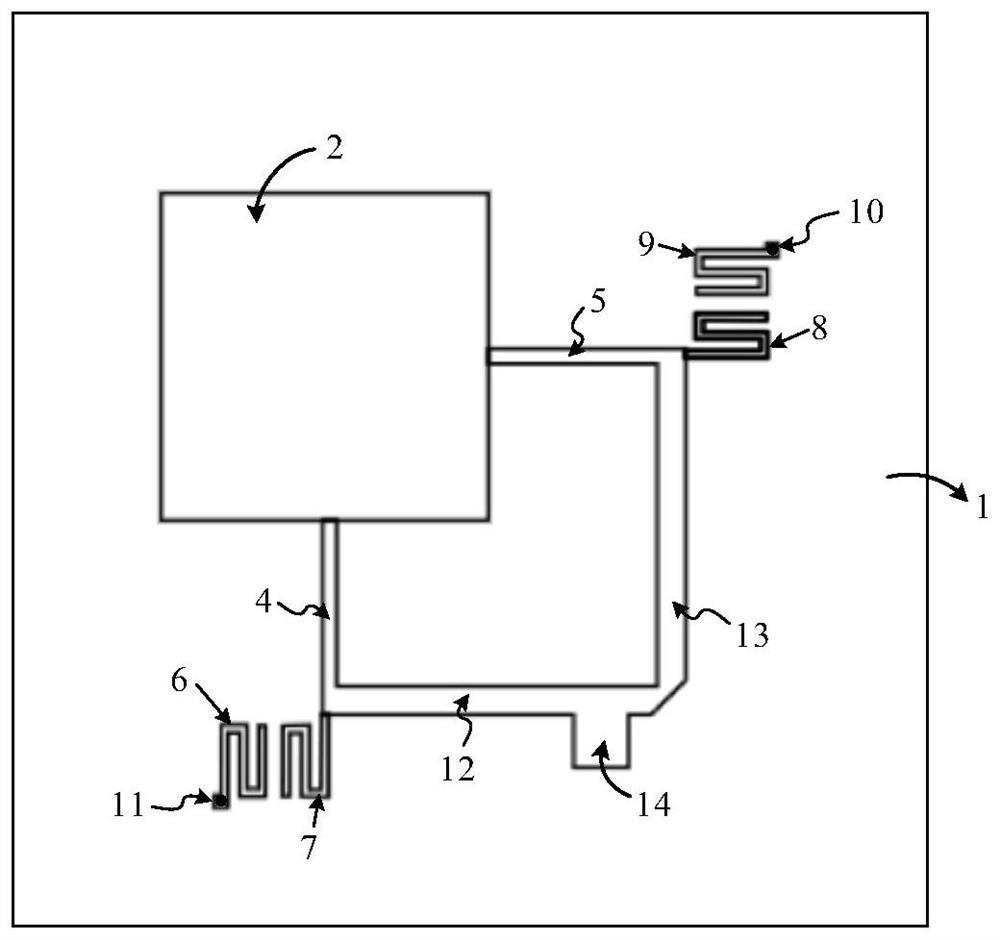
[0030] Such as figure 1 and figure 2 As shown, a broadband circularly polarized patch antenna includes a dielectric substrate 1 with a thickness smaller than the wavelength of the operating frequency point, a square metal patch element 2, a microstrip line, multiple groups of folded coupling lines, a three-dimensional metal floor 3 and Metal vias; the square metal patch element 2, the microstrip line and the folded coupling line group are all located on the surface of the dielectric substrate 1, and the three-dimensional metal floor 3 is located on the surface of the dielectric substrate 1 On the other surface, both the square metal patch element 2 and the folded coupling line group are connected to the microstrip line, and the metal via penetrates one end of the dielectric substrate 1 and is connected to the folded c...


PUM


Abstract

The invention discloses a broadband circularly polarized patch antenna, which comprises a dielectric substrate, a square metal patch element, a microstrip line, a plurality of folding coupling line groups, a three-dimensional metal floor and a plurality of metal via holes, the square metal patch element, the microstrip line and the folding coupling line group are all located on the surface of the dielectric substrate, the three-dimensional metal floor is located on the other surface of the dielectric substrate, the square metal patch element is connected with the microstrip line, the microstrip line is connected with the folding coupling line group, and the metal via hole penetrates through one end of the dielectric substrate and is connected with the folding coupling line group to form a parallel resonator. And the other end is connected with the three-dimensional metal floor. According to the invention, the parallel resonator structure formed by the metal via holes and the folding coupling line group is added, so that the purpose of expanding the broadband characteristic is achieved; meanwhile, parasitic radiation of the feed circuit is reduced in a mode that the microstrip line is directly connected with the antenna; and the antenna radiation unit and the feed circuit can be placed on the same surface of the dielectric substrate, so that processing and assembling are facilitated.

Description

technical field [0001] The invention belongs to the field of microwave communication, and in particular relates to a broadband circularly polarized patch antenna. Background technique [0002] Circularly polarized patch antennas are widely used in satellite communications and GPS positioning. With the continuous upgrading of wireless communication systems, new applications place higher and higher requirements on the performance of antennas in wireless communication systems. The operating bandwidth of circularly polarized antennas is getting wider and wider. More antenna elements need to be integrated in a smaller space, so the feed circuit of the antenna needs to reduce spurious radiation, so as to reduce the impact on the overall performance of the antenna. From the perspective of market products, printing the antenna unit and the feed circuit on the same dielectric substrate can reduce the cost of processing and assembly. [0003] Traditional broadband circularly polari...

Claims


Application Information

Patent Timeline
Patent Type & Authority Applications(China)
IPC IPC(8): H01Q1/38H01Q1/50H01Q1/48H01P7/08
CPCH01Q9/0428
Inventor 吴琼森章国豪
Owner SYNERGY INNOVATION INST OF GDUT HEYUAN
Why Eureka
Try Eureka