New energy storage device

A storage device and new energy technology, applied in the field of electrochemical energy storage, can solve the problems of reducing the practicability of equipment, real-time observation of the status of difficult-to-store items, and fixing the angle of solar panels, so as to achieve convenient monitoring and access, and improve power generation. Efficiency and functional diversification

Pending Publication Date: 2022-04-15
STATE NUCLEAR ELECTRIC POWER PLANNING DESIGN & RES INST CO LTD
View PDF0 Cites 0 Cited by
  • Summary
  • Abstract
  • Description
  • Claims
  • Application Information

AI Technical Summary

Problems solved by technology

[0003] There are many types of new energy storage devices on the market today, which can basically meet people's needs, but there are still some shortcomings. The specific problems are as follows: (1) Most of the existing new energy storage devices use solar energy To generate electricity, solar energy is used as the energy source of the equipment to supply power to the equipment. However, the angle of the solar panel on the existing new energy storage equipment is fixed, and the power generation efficiency is low; (2) When the existing new energy storage equipment is in use, the internal storage It is necessary to reach into the interior of the storage device to pick up the items, which reduces the convenience of use, and the distance between the partitions of the equipment is fixed, making it difficult to store large-sized items, which reduces the practicability of the equipment; (3) the existing new energy storage Object equipment has high temperature requirements when storing special items, and it is difficult to observe the status of stored items in real time
[0004] Therefore, the existing new energy storage devices cannot meet people's diverse use needs, and the comprehensive performance of new energy storage devices needs to be improved

Method used


Image

  • New energy storage device
  • New energy storage device
  • New energy storage device

Examples


Embodiment Construction

[0030] In order to make the purpose, technical solutions and advantages of the embodiments of the present invention more clear, the technical solutions in the embodiments of the present invention will be clearly and completely described below in conjunction with the accompanying drawings in the embodiments of the present invention. Obviously, the described embodiments It is a part of embodiments of the present invention, but not all embodiments. Based on the embodiments of the present invention, all other embodiments obtained by persons of ordinary skill in the art without making creative efforts belong to the protection scope of the present invention.

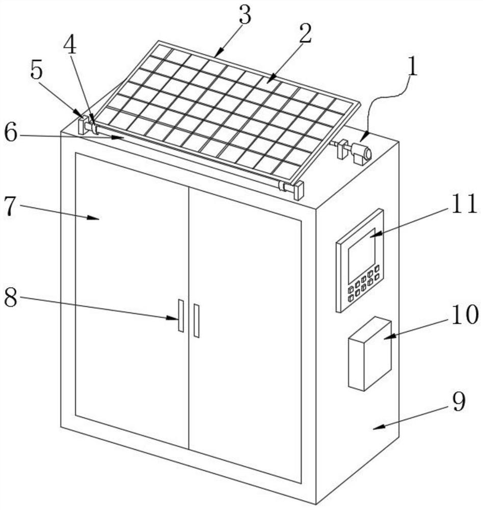
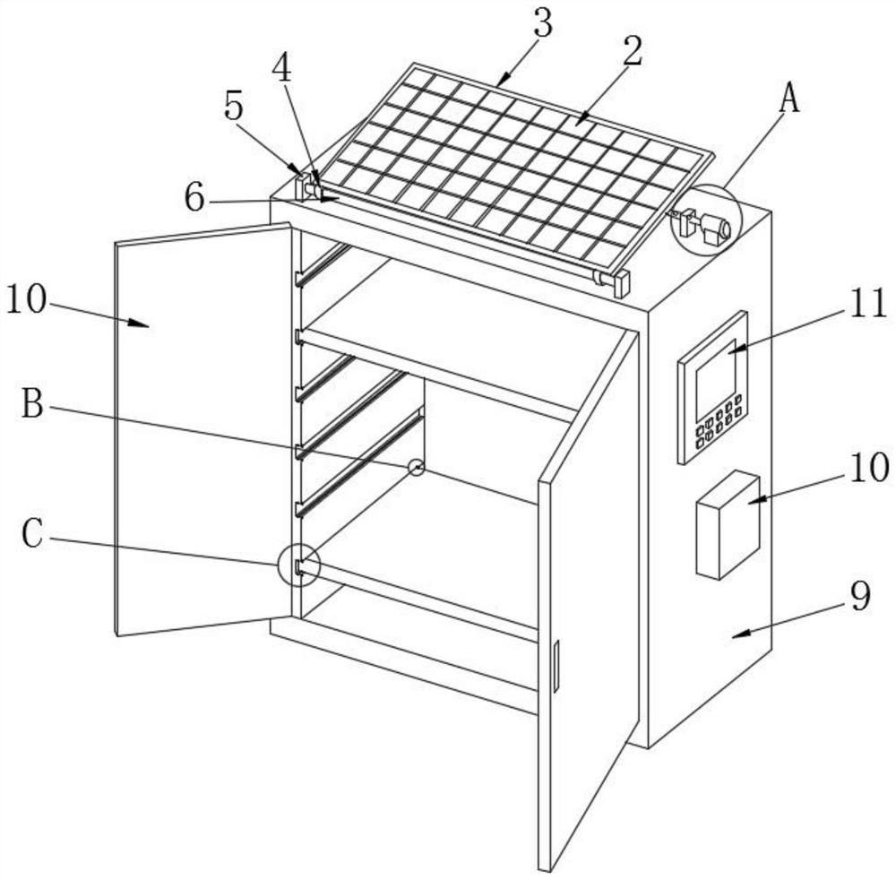
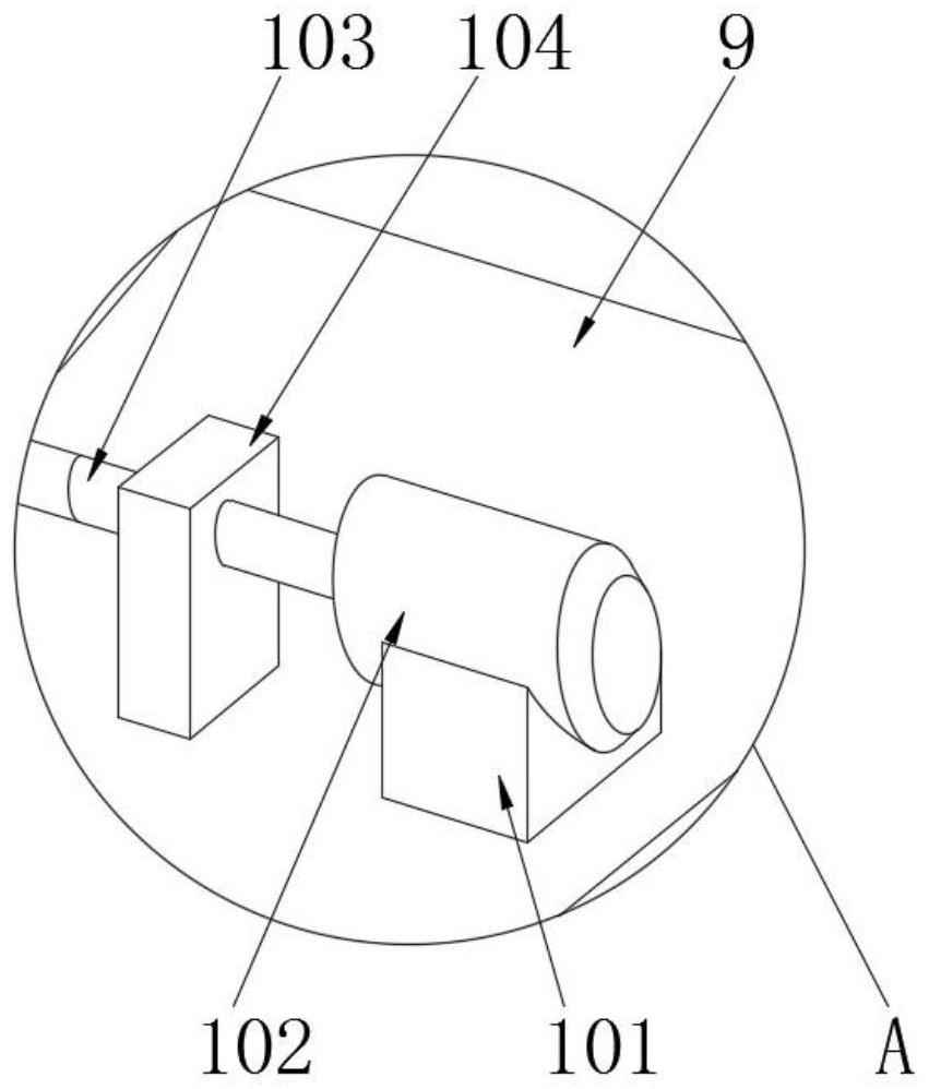
[0031] A new energy storage device based on the Internet of Things, such as figure 1 As shown, the device includes a locker 9, a mounting plate 3, a solar cell panel 2 and an angle adjustment mechanism 1, and the two ends of the connecting shaft 6 are respectively provided with a second fixed block 5, and the connecting shaft ...


PUM


Abstract

The invention provides a new energy storage device which comprises a storage cabinet, a mounting plate, a solar cell panel and an angle adjusting mechanism, a connecting shaft is rotatably mounted on the storage cabinet, one side of the mounting plate is fixedly connected with the connecting shaft, the solar cell panel is fixedly arranged on the mounting plate, one end of the angle adjusting mechanism is connected with the storage cabinet, and the other end of the angle adjusting mechanism is connected with the mounting plate. The other end of the angle adjusting mechanism is connected with the mounting plate; and a remote monitoring mechanism is arranged on the storage cabinet. Through the arrangement of the angle adjusting mechanism, electric adjustment of the angle of the solar cell panel is achieved, the angle of the solar cell panel can be adjusted according to the incident angle of sunlight, the power generation efficiency can be improved, new energy is adopted for supplying power to equipment, and energy conservation and environmental protection are facilitated; the remote monitoring mechanism is based on the Internet of Things, monitoring and taking are convenient, the functions are diversified, and the comprehensive performance is high.

Description

technical field [0001] The invention belongs to the technical field of electrochemical energy storage, and in particular relates to a new energy storage device. Background technique [0002] New energy, also known as unconventional energy, refers to various forms of energy other than traditional energy, and also refers to energy that has just begun to be developed and utilized or is being actively researched and yet to be promoted, such as solar energy, geothermal energy, wind energy, ocean energy, and biomass energy. And nuclear fusion energy, etc., the application range of new energy is very wide, and it is also used in storage equipment. [0003] There are many types of new energy storage devices on the market today, which can basically meet people's needs, but there are still some shortcomings. The specific problems are as follows: (1) Most of the existing new energy storage devices use solar energy To generate electricity, solar energy is used as the energy source of t...

Claims


Application Information

Patent Timeline
IPC IPC(8): A47B81/00A47B57/10A47B47/00A47B95/00A47B97/00H02J7/35H02S20/30
CPCA47B81/00A47B47/00A47B57/10A47B97/00A47B95/00H02S20/30H02J7/35Y02E10/50Y02P80/20
Inventor 张建友席爱斌薛涛冯震坤王长山刘伟李亿杜蓉
Owner STATE NUCLEAR ELECTRIC POWER PLANNING DESIGN & RES INST CO LTD
Why Eureka
Try Eureka