Adjustable combined boring head

A boring head and rough boring technology, which is applied in the field of adjustable combined boring head, can solve the problems that fine boring cannot achieve surface roughness, the pass rate cannot be guaranteed, and it is not conducive to rapid production, so as to reduce the wear rate of machine tools and reduce electricity expenses , Processing quality and reliable effect

Pending Publication Date: 2022-04-15
SHANDONG LAIWU COAL MINING MACHINERY
View PDF11 Cites 1 Cited by
  • Summary
  • Abstract
  • Description
  • Claims
  • Application Information

AI Technical Summary

Problems solved by technology

[0002] When processing the inner hole of the workpiece, it needs to go through two processes of rough boring and fine boring, but in some cases, fine boring cannot meet the requirements of surface roughness, and a rolling process needs to be added; Among them, rough boring tools, fine boring tools and rollers need to be used, and processing tools need to be frequently replaced on the boring bar, which causes complicated processing procedures and reduces processing efficiency
The existing technology needs to adjust the rough boring tool, fine boring tool and roller separately. The roller adjustment needs to adjust the rear limit stop to the front of the roller, and it is necessary to pad the tough part of the rough boring tool and the fine boring tool with copper skin. Reduce the scratches when the machined hole is retracted, and the processing efficiency is improved, but the pass rate cannot be guaranteed, and the steps are more cumbersome, which is not conducive to rapid production

Method used


Image

  • Adjustable combined boring head
  • Adjustable combined boring head
  • Adjustable combined boring head

Examples


Embodiment Construction

[0025] In order for those skilled in the art to better understand the technical solution of the present application, the technical solution of the present application is clearly and completely described below in conjunction with the accompanying drawings of the present application. Based on the embodiments in the present application, those of ordinary skill in the art can Other similar embodiments obtained without creative work shall all fall within the scope of protection of this application. In addition, the directional words mentioned in the following embodiments, such as "upper", "lower", "left", "right", etc., are only referring to the directions of the drawings, therefore, the directional words used are for illustration rather than limitation Application to create.

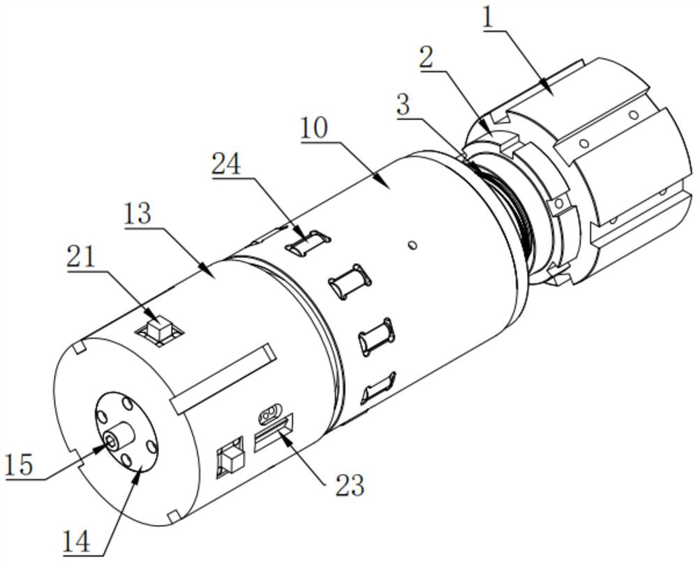
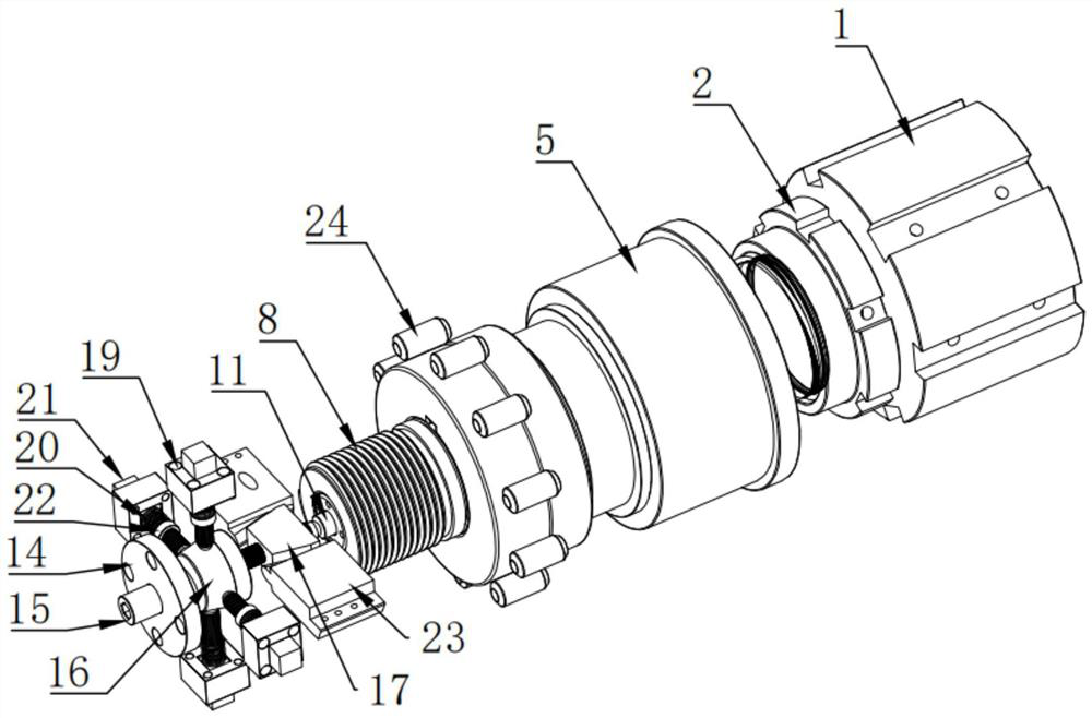
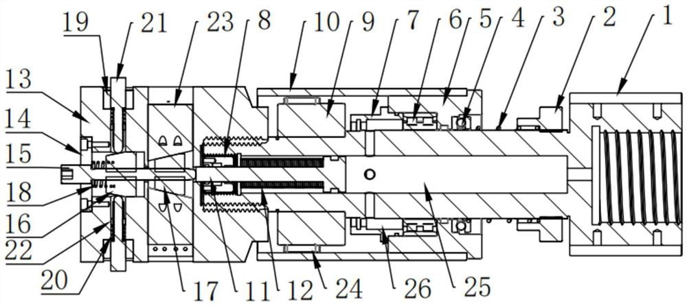
[0026] Such as Figure 1-3 As shown, an adjustable combined boring head includes a boring head piston rod 1, a boring head body 13 slidingly socketed on the outside of the boring head piston rod 1, and a pu...


PUM


Abstract

The invention belongs to the technical field of inner hole machining, and particularly discloses an adjustable combined boring head which comprises a boring head piston rod, a boring head body slidably connected to the outer side of the boring head piston rod in a sleeving mode and a push broach piston rod slidably connected to the inner side of the boring head piston rod in a sleeving mode. An adjusting screw rod is arranged at the axis of the end part of the boring head body, a rough boring adjusting expansion block and a fine boring adjusting expansion block which are matched with the rough boring cutter and the fine boring cutter are respectively in threaded connection with the adjusting screw rod, the expansion directions of the rough boring adjusting expansion block and the fine boring adjusting expansion block are the same, one end of the adjusting screw rod is in threaded connection with the boring head body, and the other end of the adjusting screw rod is in threaded connection with the boring head body. And the other end is propped against the output end of the push broach piston rod. The purposes of hydraulic automatic adjustment, improvement of operation safety of a machine tool and improvement of boring efficiency are achieved, the inner hole of the cylinder barrel is sequentially machined from rough boring to fine boring to tumbling, the electric charge expenditure is reduced, the abrasion rate of the machine tool is reduced, the labor intensity is reduced, and the working safety is guaranteed.

Description

technical field [0001] The application belongs to the technical field of inner hole processing, and in particular relates to an adjustable combined boring head. Background technique [0002] When processing the inner hole of the workpiece, it needs to go through two processes of rough boring and fine boring, but in some cases, fine boring cannot meet the requirements of surface roughness, and a rolling process needs to be added; Among them, rough boring cutters, fine boring cutters and rollers need to be used, and processing tools need to be frequently replaced on the boring bar, which causes complicated processing procedures and reduces processing efficiency. The existing technology needs to adjust the rough boring tool, fine boring tool and roller separately. The roller adjustment needs to adjust the rear limit stop to the front of the roller, and it is necessary to pad the tough part of the rough boring tool and the fine boring tool with copper skin. Reducing the scratch...

Claims


Application Information

Patent Timeline
Patent Type & Authority Applications(China)
IPC IPC(8): B23B29/034B23B41/02B23B51/08B23P9/02
Inventor 马繁胜张庆王鑫李刚陈恽史晓晖亓宏展孙厚新张伦明刘会国牛晓峰蔺磊杨敏亓子玉胡宗辉祝海涛
Owner SHANDONG LAIWU COAL MINING MACHINERY
Why Eureka
Try Eureka