
Device and method for dynamically measuring greenhouse gas emission flux of water body

A technology of greenhouse gas and emission flux, which is applied in measurement devices, sampling devices, and the dynamic effect of fluid flow detection, etc., can solve the problems of inability to achieve synchronous measurement, inability to achieve continuous flux measurement, etc., and avoid emission flux. Determining the effect of distortion

Pending Publication Date: 2022-04-15
RES CENT FOR ECO ENVIRONMENTAL SCI THE CHINESE ACAD OF SCI
View PDF9 Cites 2 Cited by
  • Summary
  • Abstract
  • Description
  • Claims
  • Application Information

AI Technical Summary

Problems solved by technology

[0006] Therefore, the technical problem to be solved by the present invention is to overcome the following defects in the water body greenhouse gas emission flux measurement technology represented by the static floating tank technology: the simultaneous measurement of the greenhouse gas flux released in the form of bubbles and the flux released through the diffusion process cannot be realized. of greenhouse gas fluxes; continuous flux measurements cannot be achieved; the concentration of the air above the water surface has to be changed to affect the diffusion process

Method used


Image

  • Device and method for dynamically measuring greenhouse gas emission flux of water body
  • Device and method for dynamically measuring greenhouse gas emission flux of water body
  • Device and method for dynamically measuring greenhouse gas emission flux of water body

Examples


Embodiment 1

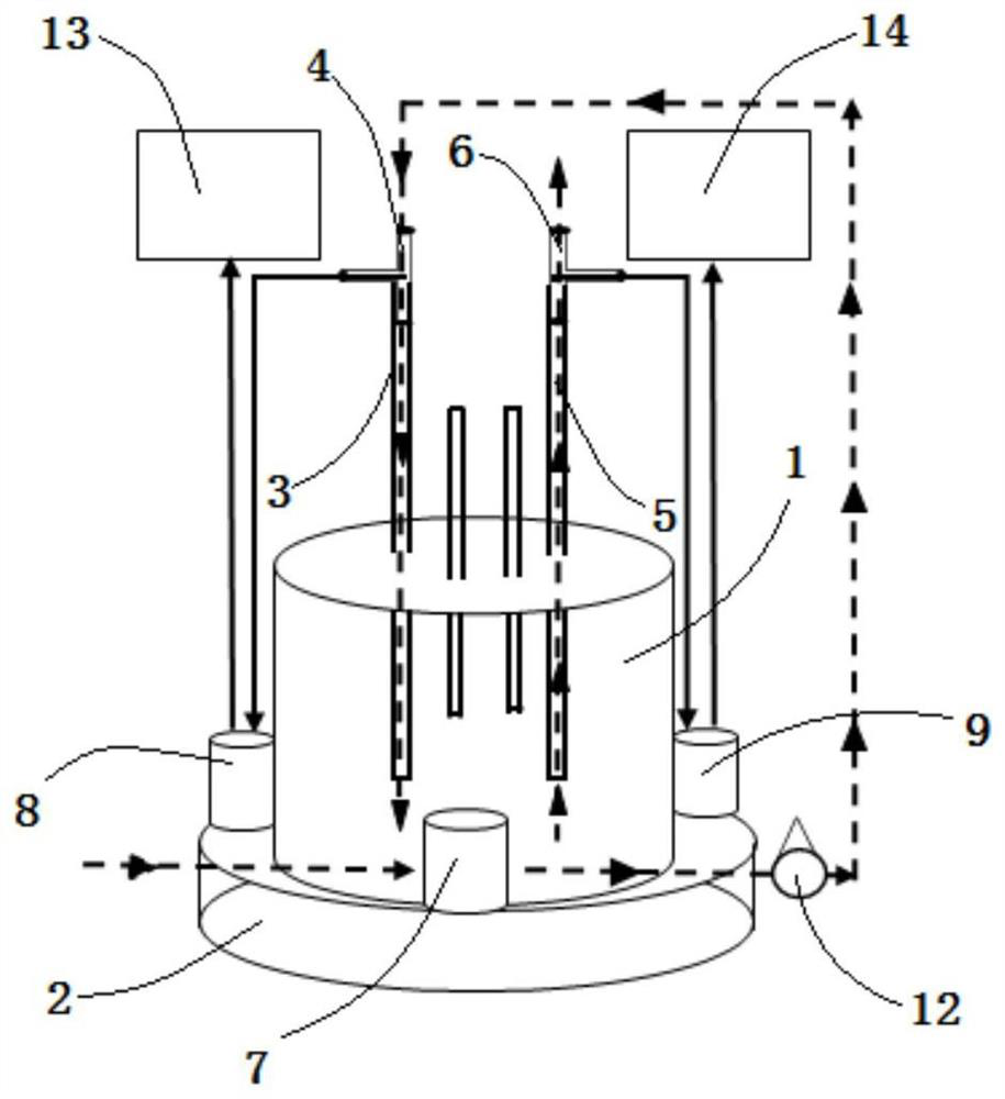
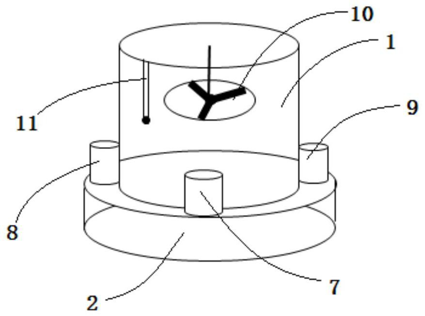
[0095] Such as figure 1 and 2 As shown, the present embodiment provides a device for dynamically measuring the emission flux of greenhouse gases in water bodies, which consists of the following parts:

[0096] The box body 1 is composed of a side surface and a bottom surface, the top forms an open end, and the bottom surface forms a closed end, the box body 1 is cylindrical, the material is stainless steel, and the volume of the box body 1 is 20L;

[0097] The floating platform 2 is arranged on the box body 1 so that the open end of the box body 1 contacts the water surface. It is a floating ring formed around the open end of the box body 1. One end of the floating ring is flush with the open end of the box body 1. The floating platform 2 using inflatable rubber ring;

[0098] The air intake pipe 3 communicates with the inside of the box body 1, and its end outside the box body 1 is connected with an air intake pipe three-way valve 4, and the air intake pipe 3 is arranged at...

Embodiment 2

[0107] This embodiment provides a method for dynamically measuring the flux of greenhouse gas emissions in water bodies. The device provided in Embodiment 1 is used for measurement. The steps are as follows:

[0108] (1) The open end of the box body 1 of the device is placed on the water surface of the water body to be measured towards the water body to be measured, and a sampling space of about 20L is formed inside the box body 1;

[0109] (2) Turn on the air intake pump 7, so that the gas on the surface of the water body enters the box body 1 through the air intake pump 7, the three-way valve 4 of the air intake pipe, and the air intake pipe 3 to form an air intake path, and the gas in the box body 1 passes through the air outlet in sequence. The air pipe 5 and the three-way valve 6 of the air outlet pipe are discharged to the outside of the box body 1 to form an air outlet path. Gas, where the gas flow rate of the air intake path is adjusted to 2L / min;

[0110] (3) Simulta...


PUM

PropertyMeasurementUnit
heightaaaaaaaaaa

Abstract

The invention provides a device and a method for dynamically measuring greenhouse gas emission flux of a water body, and relates to the field of environmental protection. The device comprises a box body, a floating platform, an air inlet pipe, an air outlet pipe, an air inlet pump, an air inlet pipe sampling air pump and an air outlet pipe sampling air pump. Discharge flux measurement distortion caused by excessive accumulation of greenhouse gas due to strong release of a water body in the box body is effectively avoided; the greenhouse gas released by bubbles and a water-gas interface at any time can be captured, so that the technical problem that a static buoyancy tank technology cannot synchronously realize water bubble greenhouse gas release and water-gas interface greenhouse gas exchange flux measurement can be solved; the time variability of water body greenhouse gas emission can be finely reflected, and long-time uninterrupted measurement of the water body greenhouse gas emission flux can be realized, so that uncertainty of a measurement result caused by low-frequency measurement of the water body greenhouse gas emission flux by a static buoyancy tank technology is effectively avoided, and manpower and instrument test resources can be greatly saved.

Description

technical field [0001] The invention relates to the technical field of environmental protection, in particular to a device and method for dynamically measuring the emission flux of greenhouse gases in water bodies. Background technique [0002] Since the industrial revolution, atmospheric carbon dioxide (CO 2 ), methane (CH 4 ) and nitrous oxide (N 2 The concentration of greenhouse gases such as O) has shown a significant increase year by year trend, and has caused a series of global environmental problems such as global warming, glacier melting, and sea level rise, and has posed a serious threat to the ecological environment on which human beings depend. At present, people still have great uncertainty in estimating the sources of greenhouse gases, and it is still necessary to develop and improve existing monitoring technologies to reduce the uncertainty in estimating greenhouse gas source emissions. [0003] Water bodies are an important source of methane emissions, acco...

Claims


Application Information

Patent Timeline
Patent Type & Authority Applications(China)
IPC IPC(8): G01N1/24G01N33/00G01F1/22
CPCY02A50/20
Inventor 曲久辉牟济春胡承志于洪伟牟玉静
Owner RES CENT FOR ECO ENVIRONMENTAL SCI THE CHINESE ACAD OF SCI
Learn More