
Master-slave cooperative positioning and clamping device for realizing near-zero sliding of high-speed rail gear shaft

A technology of co-location and clamping device, applied in the direction of gear teeth manufacturing device, components with teeth, belt/chain/gear, etc., can solve impact and sliding, high shape accuracy and surface quality, machining track deviation, etc. problems, achieve the effects of suppressing the impact and sliding of the gear shaft, high shape accuracy and surface quality, and reducing machining errors

Pending Publication Date: 2022-04-19
SOUTHWEST JIAOTONG UNIV
View PDF7 Cites 5 Cited by
  • Summary
  • Abstract
  • Description
  • Claims
  • Application Information

AI Technical Summary

Problems solved by technology

[0006] 1. The gear shaft is clamped by a three-jaw chuck. The center line of the gear shaft is easy to deviate from the center line of the chuck, which cannot guarantee the high shape accuracy and surface quality of the tooth surface of the gear shaft during polishing.
[0007] 2. If the clamping force of the three-jaw chuck is too large, the surface of the gear shaft will be clamped. If the clamping force of the three-jaw chuck is not enough, impact and sliding may occur between the chuck body and the gear shaft, resulting in deviation of the machining track. High shape accuracy and surface quality of the tooth surface of the gear shaft during polishing cannot be guaranteed
[0008] The existing positioning and clamping devices used in gear shaping finishing usually use liquid plastic centering and clamping methods, and the gear shaft is installed in a thin-walled sleeve based on the outer cylindrical surface and end surface of the gear shaft. The space between the thin-walled sleeve and the clamp body is filled with liquid plastic. By tightening the screw, the plunger moves to squeeze the liquid plastic, so that the liquid plastic is stressed, and the thin-walled sleeve produces uniform elastic deformation, and the gear shaft is centered in the clamp. However, in the actual application process, the structure of the device is complicated, there are many steps for loading and unloading the gear shaft, and the manufacturing and maintenance costs are high
[0009] As mentioned above, none of the existing positioning and clamping devices can meet the technical requirements of ultra-precision CNC polishing of the tooth surface of the gear shaft. Problems with the device

Method used


Image

  • Master-slave cooperative positioning and clamping device for realizing near-zero sliding of high-speed rail gear shaft
  • Master-slave cooperative positioning and clamping device for realizing near-zero sliding of high-speed rail gear shaft
  • Master-slave cooperative positioning and clamping device for realizing near-zero sliding of high-speed rail gear shaft

Examples


no. 1 example

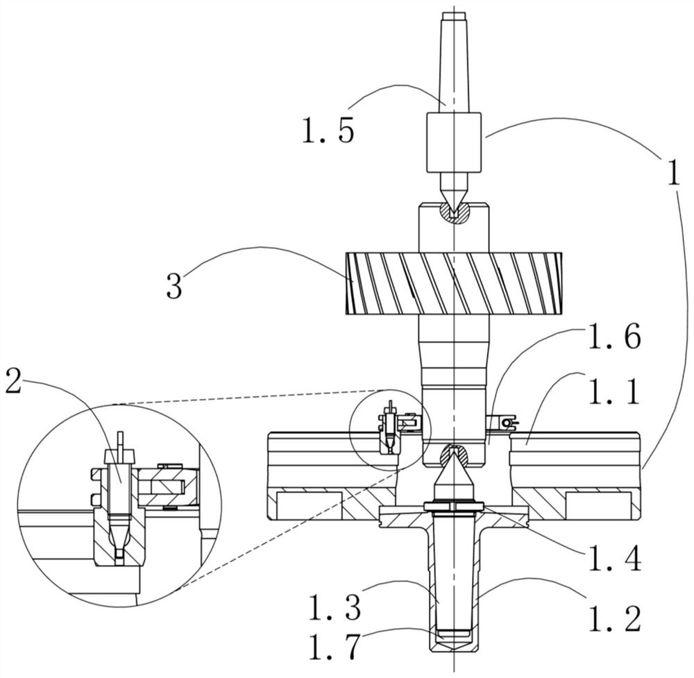
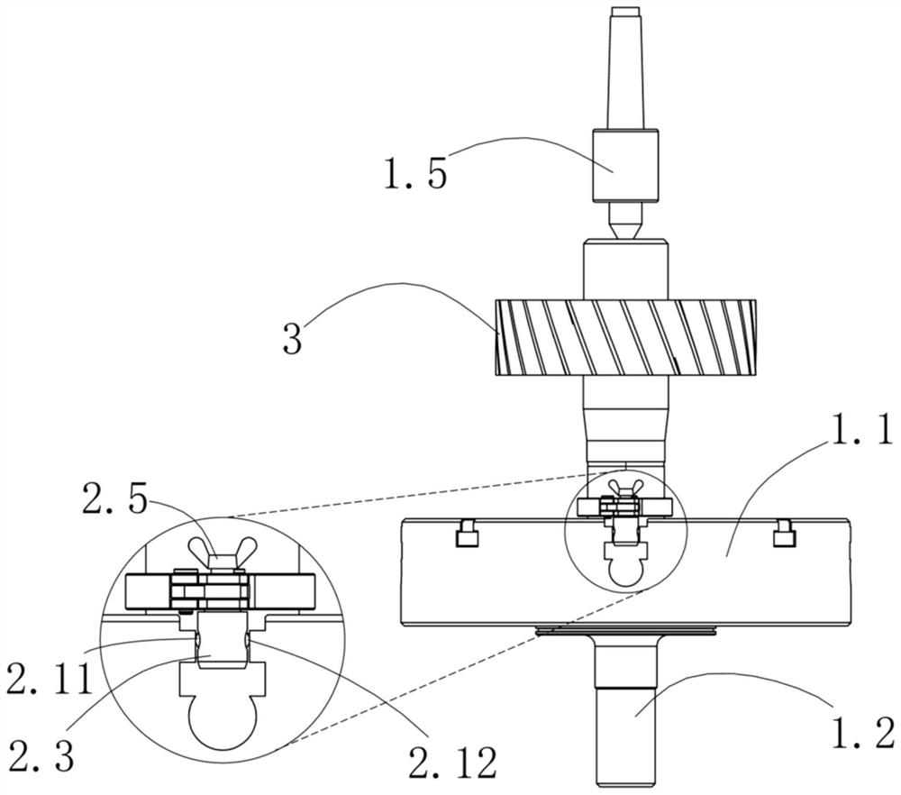
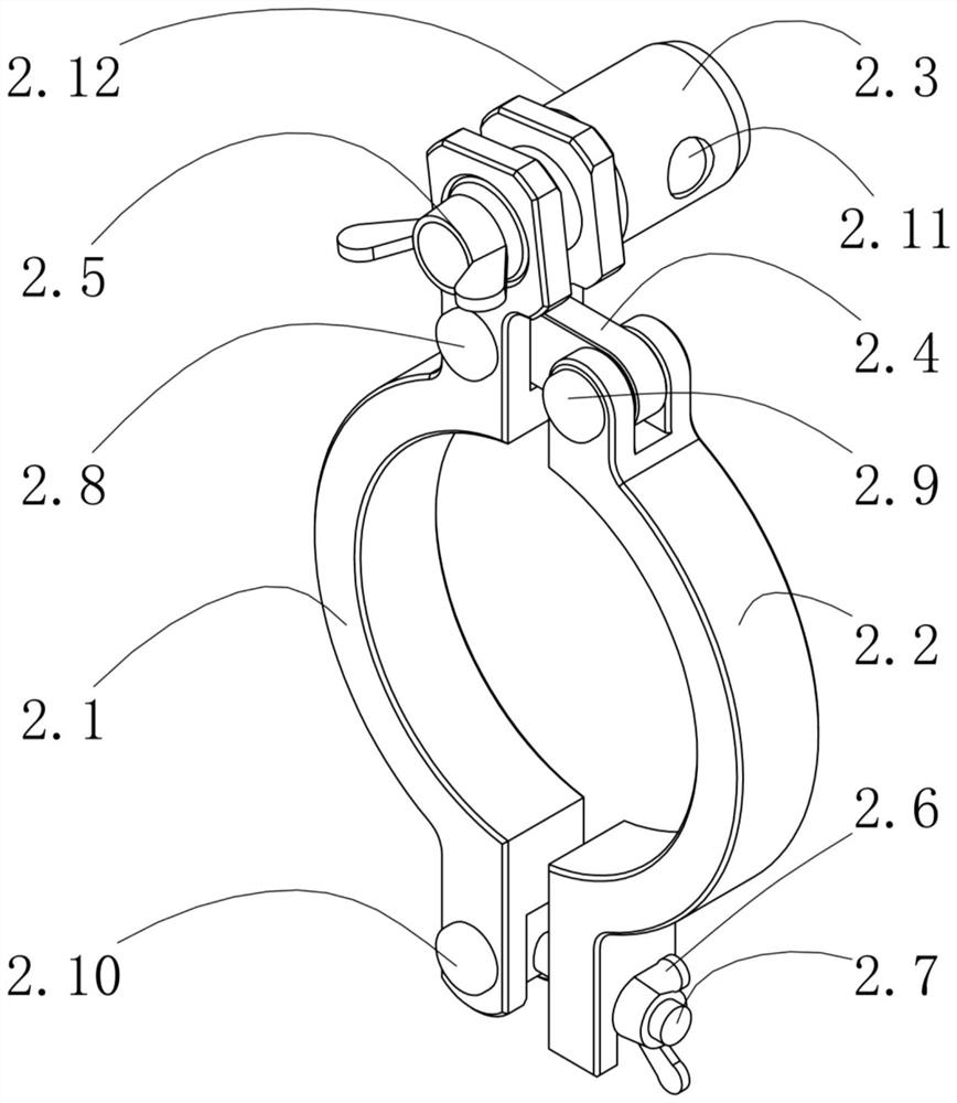
[0034] Such as Figure 1 to Figure 5 As shown, the present invention provides a master-slave cooperative positioning clamping device that realizes near-zero sliding of the high-speed rail gear shaft, including a master positioning center assembly 1 and a slave positioning journal chuck assembly 2, and the master positioning center assembly 1 is used to realize the gear The axial positioning and radial positioning of the shaft 3, wherein the chuck 1.1, the chuck positioning plate 1.2, the lower center 1.3 and the round nut 1.4 are clamp bodies, and the chuck assembly 2 of the positioning journal is used to realize the circumferential positioning of the gear shaft 3, One end clamps the gear shaft 3, and the other end is clamped and fixed with the chuck 1.1. Through the synergistic effect of the main positioning tip assembly 1 and the secondary positioning journal chuck assembly 2, the six degrees of freedom of the gear shaft 3 are limited, that is, along the x The degree of free...


PUM

PropertyMeasurementUnit
diameteraaaaaaaaaa

Abstract

The invention discloses a master-slave cooperative positioning and clamping device for realizing near-zero sliding of a high-speed rail gear shaft, which comprises a master positioning tip assembly and a slave positioning shaft neck chuck assembly, the master positioning tip assembly is used for realizing axial positioning and radial positioning of the gear shaft, and a chuck, a chuck positioning plate, a lower tip and a round nut are clamp bodies. The clamp body is connected with a motor shaft through a transmission system, the slave positioning shaft neck chuck assembly is used for achieving circumferential positioning of a gear shaft, one end of the slave positioning shaft neck chuck assembly clamps the gear shaft, the other end of the slave positioning shaft neck chuck assembly is fixedly clamped with a chuck, and six degrees of freedom of the gear shaft are limited through master-slave cooperative positioning. By using the device, the gear shaft is convenient to assemble and disassemble and high in positioning precision; through the technical scheme, near-zero sliding positioning and clamping between the gear shaft and the clamp body are achieved, gear shaft impact and sliding caused by sudden change of the speed of the clamp body are restrained, then highly synchronous rotation of the gear shaft and a motor shaft is achieved, and the high shape precision and surface quality of the tooth surface of the gear shaft during ultra-precision numerical control polishing are guaranteed.

Description

technical field [0001] The invention relates to the field of gear manufacturing, in particular to a master-slave cooperative positioning clamping device for realizing near-zero sliding of a high-speed rail gear shaft. Background technique [0002] High-speed rail is a golden business card made in China. As the core component of high-speed train energy transmission, the gear transmission system's reliability and stability directly affect the safe operation of the train. At present, there are more than 50,000 sets of high-speed rail gear transmission systems in service in China, and 80% of the existing problems and failures come from lubrication failure. For the gearbox of the next-generation high-speed train with a speed of 400 kilometers per hour, the traditional lubrication technology is difficult to support the technical upgrade and product generation of the gearbox. Therefore, a new technological change is proposed to replace the traditional lubrication with solid-liquid...

Claims


Application Information

Patent Timeline
Patent Type & Authority Applications(China)
IPC IPC(8): B23F23/06B23F19/00
CPCB23F23/06B23F19/00
Inventor 江亮谢鸿升钱林茂晏璐文叶夫义
Owner SOUTHWEST JIAOTONG UNIV
Learn More