Control method of header system coke oven flue gas recovery system

A flue gas recovery and control method technology, which is applied in the field of heat recovery coke ovens, can solve problems such as violation of environmental protection, environmental pollution, and waste of waste heat resources, so as to save expensive costs, improve stability and reliability, and reduce The effect of footprint

Pending Publication Date: 2022-04-22
福建三钢闽光股份有限公司 +1
0 Cites 0 Cited by

AI-Extracted Technical Summary

Problems solved by technology

When the waste heat boiler or desulfurization system is overhauled, the flue gas is directly discharged from the high-temperature chimney through the bypass pipe, but the sulfur content of the flue gas without desulfurization is...

Method used

Referring to Fig. 2, flue gas main pipe 3 comprises first flue gas main pipe 31 and second flue gas main pipe 32; First flue gas main pipe 31 is provided with at least two first flue gas inlets 311 and at least two a first flue gas outlet 312; the second flue gas main pipe 32 is provided with at least two second flue gas inlets 321 and at least two second flue gas outlets 322; each first waste heat boiler 21 is independently connected to the first The flue gas inlet 311 ; each second waste heat boiler 22 is independently connected to the second flue gas inlet 321 ; the first flue gas outlet 312 and the second flue gas outlet 322 located adjacent to each other are connected to the same desulfurization device 4 . The flue gas main pipe 3 of the present invention is composed of a first flue gas main pipe 31 and a second flue gas main pipe 32, which can receive flue gas from the first waste heat boiler 21 and the second waste heat boiler 22 respectively, and Evenly distributed to multiple desulfurization units 4 for processing. This design can simultaneously overhaul the first waste heat boiler 21 or the second waste heat boiler 22 of all boiler groups 2, which can realize regular batch maintenance of boiler groups 2, which helps to optimize the maintenance process, improve maintenance efficiency, and reduce System control difficulty.
With reference to Fig. 2 and Fig. 3, in the present embodiment, the quantity of boiler group 2 is 3, comprises 1# boiler among the figure and 2# boiler, 3# boiler and 4# boiler, 5# boiler and 6 #boiler. Each boiler group 2 is connected to two coke oven groups 1, of which 1# boiler and 2# boiler are connected to 1-4# coke ovens at the same time; 3# boiler and 4# boiler are connected to 5-8# coke ovens at the same time; 5 # boiler and 6# boiler are connected to 9-12# coke oven at the same time. Such layout can make full use of each waste heat boiler, which is beneficial to improve economic benefits. According to actual production experience, the flue gas produced by the coke oven is high-temperature flue gas, with a flue gas temperature as high as 850-1200°C. 180°C, so in order to further shorten the length of the high-temperature pipeline and reduce the heat transfer distance and heat loss of the high-te...

Abstract

The invention discloses a control method of a header system coke oven flue gas recovery system. The control method comprises the following steps: 1, discharging flue gas generated by a coke oven group into a boiler group for waste heat recovery treatment; 2, the flue gas treated by the boiler group is gathered in a flue gas main pipe through a flue gas inlet; and 3, the flue gas gathered in the flue gas mother pipe is shunted to each desulfurization device through each flue gas outlet to be subjected to desulfurization treatment until reaching the standard, and then is discharged. The flue gas header system is innovatively introduced for flue gas waste heat recovery and desulfurization treatment of the coke oven, and when one boiler group or desulfurization device needs to be overhauled, other boiler groups and desulfurization devices can still continue to operate, so that flue gas generated by other coke oven groups can be effectively treated in time, and the energy consumption is reduced. And the defects in the prior art are overcome.

Application Domain

Dispersed particle separationSteam generation using hot heat carriers

Technology Topic

Process engineeringFlue gas +6

Image

  • Control method of header system coke oven flue gas recovery system
  • Control method of header system coke oven flue gas recovery system
  • Control method of header system coke oven flue gas recovery system

Examples

  • Experimental program(1)

Example Embodiment

[0038] The following specific embodiments of the present invention are illustrated with reference to the accompanying drawings.
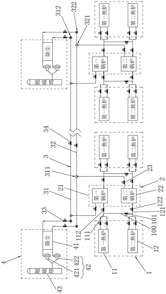
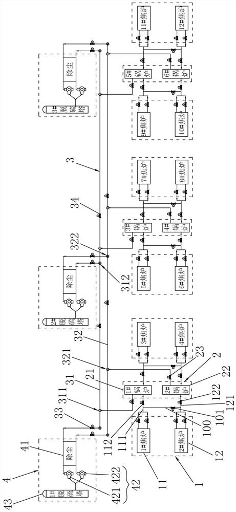
[0039] Reference Figure 2 , a mother control coke oven flue gas recovery system, comprising a coke oven group 1, boiler group 2, flue gas bus tube 3 and desulfurization device 4; each boiler group 2 is connected to at least one coke oven group 1; flue gas bus tube 3 has at least two flue gas inlets and at least two flue gas outlets; each flue gas inlet is connected to a boiler group 2, each flue gas outlet is connected to a desulfurization device 4. Each boiler group 2 will be coke oven group 1 generated by the high temperature flue gas heat exchange cooling into low temperature flue gas and then discharged into the flue gas mother tube 3 confluence, and then from the flue gas mother tube 3 to each desulfurization device 4 for desulfurization treatment. When one of the boiler group 2 or desulfurization unit 4 needs to be overhauled, the other boiler group 2 and the desulfurization unit 4 can still continue to operate, thereby ensuring that the flue gas generated by the other coke oven group 1 can be treated in a timely and effective manner, overcoming the defects of the prior art.
[0040] Reference Figure 2 , the boiler set 2 comprises a first waste heat boiler 21 and a second waste heat boiler 22; coke oven group 1 includes a first coke oven 11 and a second coke oven 12; the first coke oven 11 is connected to the first waste heat boiler 21 through the first flue gas pipeline 111; the second coke oven 12 is connected to the second waste heat boiler 22 through the second flue gas pipe 121; and the first flue gas pipe 111 and the second flue gas pipe 121 are connected through the flue gas branch pipe 100. The present invention has two juxtaposed waste heat boilers for each boiler set 2, when one of the waste heat boilers needs to be overhauled, the flue gas generated by the coke oven may be introduced into another waste heat boiler for waste heat recovery treatment. It can be seen that the practicality of this can avoid the situation of suspension of production due to waste heat boiler maintenance, and can fully improve the production efficiency under the condition of ensuring that the flue gas is effectively treated.
[0041] Reference Figure 2 and Figure 3 , in the present embodiment, the number of boiler group 2 is 3, including 1# boiler and 2# boiler in FIG. 3# boiler and 4# boiler, 5# boiler and 6# boiler. Each boiler group 2 is connected to two coke oven groups 1, of which the 1# boiler and the 2# boiler are simultaneously connected to the 1-4# coke oven; the 3# boiler and the 4# boiler are simultaneously connected to the 5-8# coke oven; the 5# boiler and the 6# boiler are simultaneously connected to the 9-12# coke oven. This arrangement can make full use of each waste heat boiler, which is conducive to improving economic efficiency. According to the actual production experience can be known, the flue gas produced by the coke oven is high temperature flue gas, flue gas temperature up to 850-1200 ° C, high temperature flue gas by the waste heat boiler heat exchange cooling, can become low temperature flue gas, the flue gas temperature is as low as 180 ° C, so in order to further shorten the length of the high temperature pipeline, reduce the heat transmission distance and heat loss of high temperature flue gas, the present embodiment of the boiler group 2 is provided above the furnace table of the two coke oven group 2, for example Figure 3 As shown, the 1# boiler and the 2# boiler are set side by side with each other between the 1-4# coke oven. After many tests, it has been found that the use of such a layout can achieve the optimal layout of the pipeline on the basis of ensuring the safe and reliable operation of the system, and greatly reduce the footprint of the system, and play a significant role in cost reduction and efficiency.
[0042] Reference Figure 2 In order to facilitate remote control, each first flue gas pipeline 111 is provided with a control valve 112, each second flue gas pipeline 121 is provided with a control valve 222, each flue gas branch 100 is equipped with a control valve three 101. When the system is running, each control valve can be remotely controlled according to the specific conditions of each waste heat boiler to adjust the flow direction of high-temperature flue gas in time.
[0043] Reference Figure 2 , the flue gas mother tube 3 includes a first flue gas mother tube 31 and a second flue gas mother tube 32; the first flue gas mother tube 31 has at least two first flue gas inlets 311 and at least two first flue gas outlets 312; the second flue gas mother tube 32 has at least two second flue gas inlets 321 and at least two second flue gas outlets 322; each first waste heat boiler 21 is independently connected to the first flue gas inlet 311; each second waste heat boiler 22 is independently connected to the second flue gas inlet 321 The first flue gas outlet 312 and the second flue gas outlet 322 located adjacent to each other are jointly connected to the same desulfurization device 4. Flue gas bus tube 3 of the present invention is composed of a juxtaposed first flue gas bus 31 and a second flue gas bus 32, respectively, may receive flue gas from the first waste heat boiler 21 and the second waste heat boiler 22, and evenly distributed to a plurality of desulfurization device 4 for treatment. This design can simultaneously overhaul the first waste heat boiler 21 or the second waste heat boiler 22 of all boiler group 2, which can realize the regular batch maintenance of boiler group 2, which helps to optimize the maintenance process, improve the maintenance efficiency, and reduce the difficulty of system control.
[0044] Reference Figure 2 , the desulfurization device 4 includes a cloth strip precipitator 41, a fan unit 42 and a desulfurization tower 43 connected sequentially; the first flue gas outlet 312 and the second flue gas outlet 322 located adjacent to the same strip dust collector 41 are connected. The present invention is provided on the flue gas bus 3 at least two sets of desulfurization device 4, when one of the desulfurization device 4 needs to be overhauled, the other set of desulfurization device 4 can still operate normally, to ensure that the flue gas produced by the coke oven group 1 can be treated in a timely and effective manner. After many tests, it was found that the flue gas temperature was reduced to 58-140 ° C after desulfurization treatment, so the desulfurization tower 43 only needed to be equipped with a low-temperature chimney, and the cost of the chimney was greatly reduced, eliminating the expensive cost of additional configuration of high-temperature chimneys in the prior art.
[0045] Reference Figure 2 , the fan unit 42 includes a first fan 421 and a second fan 422; the first fan 421 and a second fan 422 are connected in parallel between the strip dust collector 41 and the desulfurization tower 43. Considering the actual production of the fan failure frequency is high, the present invention for each set of desulfurization device 4 has two fans, when one of the fans needs to be overhauled, the flue gas in the cloth dust collector 41 can be discharged to the desulfurization tower 43 through another fan, thereby ensuring that when the fan is overhauled, the desulfurization device 4 can still operate normally, playing a double insurance role, is conducive to achieving non-shutdown maintenance, fundamentally improving the stability and reliability of the system.
[0046] Reference Figure 2 and Figure 3 , the number of desulfurization device 4 in the present embodiment is 3 sets, comprising a 1# desulfurization device, a 2# desulfurization device and a 3# desulfurization device, wherein 1# desulfurization device and 3# desulfurization device is provided at both ends of the flue gas mother tube 3, 2# desulfurization device is provided in the middle of the flue gas mother tube 3. In actual production, one of the desulfurization units 4 can be selected as a backup device, which can be used during the maintenance of other desulfurization units, or all desulfurization units 4 can be opened at the same time.
[0047] Reference Figure 2 Similarly, in order to facilitate remote control, each boiler group 2 and the flue gas inlet is provided with a control valve four 23, each set of desulfurization device 4 and the flue gas outlet are equipped with a control valve five 33, and the flue gas bus tube 3 is provided between the adjacent two sets of desulfurization device 4 is provided with a control valve six 34. When the system is running, each control valve can be remotely controlled according to the specific situation of each waste heat boiler and desulfurization device 4 to adjust the flow direction of low-temperature flue gas in time.
[0048] Reference Figures 2 through 6 , the following describes the specific control method of the above-mentioned parent control coke oven flue gas recovery system:
[0049] (1) Flue gas waste heat recovery treatment: The flue gas generated by each coke oven group 1 is discharged into boiler group 2 for waste heat recovery treatment. According to the operating conditions of each boiler group 2, this step is divided into the following sub-steps:
[0050] (1.1) When all boiler groups 2 are operating normally, open the control valve 112 and control valve 122 of each boiler group 2, and close the control valve 3 101, so that the flue gas generated by the first coke oven 11 is discharged into the first waste heat boiler 21 through the first flue gas pipeline 111 for waste heat recovery treatment, and the flue gas generated by the second coke oven 12 is discharged into the second waste heat boiler 22 for waste heat recovery treatment through the second flue gas pipeline 121.
[0051] (1.2) When the first waste heat boiler 21 of a boiler group 2 needs to be overhauled, the control valve two 122 and the control valve three 101 of the boiler group 2 are opened, and the control valve 112 is closed, so that the flue gas generated by the first coke oven 11 and the second coke oven 12 of the boiler group 2 is jointly discharged into the second waste heat boiler 22 for waste heat recovery treatment.
[0052] (1.3) When the second waste heat boiler 22 of a boiler group 2 needs to be overhauled, the control valve 112 and the control valve 3 101 of the boiler group 2 are opened, and the control valve 2 122 is closed, so that the flue gas generated by the first coke oven 11 and the second coke oven 12 of the boiler group 2 is jointly discharged into the first waste heat boiler 21 for waste heat recovery treatment.
[0053] (1.4) When the first waste heat boiler 21 and the second waste heat pot 22 furnace of a boiler group 2 need to be overhauled, the control valves of the boiler group 2 are closed, two and three, and all the coke oven groups 1 corresponding to the boiler group 2 are stopped.
[0054] (2) Flue gas is collected into the flue gas mother pipe: the flue gas treated by each boiler group 2 is collected through the flue gas inlet into the flue gas mother pipe 3; specifically, the flue gas after the treatment of the first waste heat boiler 21 is collected through the first flue gas inlet 311 into the first flue gas mother pipe 31; the flue gas treated by the second waste heat boiler 21 is collected through the second flue gas inlet 321 into the second flue gas mother pipe 32.
[0055] (3) Flue gas desulfurization treatment: The flue gas collected in the flue gas mother tube is diverted through each flue gas outlet to each desulfurization device 4 after desulfurization treatment until it reaches the standard. Specifically, the flue gas gathered into the first flue gas bus 31 and the second flue gas bus 32 is diverted to the same desulfurization device 1 by the first flue gas outlet 312 and the second flue gas outlet 322 respectively for desulfurization treatment to the discharge after reaching the standard. According to the operating status of each desulfurization unit 4, the step is divided into the following sub-steps:
[0056] (3.1) When all desulfurization devices 4 are operating normally, open the control valve five 33 corresponding to each desulfurization device 4, so that the cloth dust collector 41 receives the flue gas from the first flue gas mother tube 31 and / or the second flue gas mother pipe 32, and after treatment, the flue gas is discharged into the desulfurization tower 43 at the same time by the first fan 421 and the second fan 422.
[0057] (3.2) When a desulfurization device 4 of the first fan 421 needs to be overhauled, the first fan 421 corresponding to the cloth dust collector 41 receives flue gas from the first flue gas mother tube 31 and / or the second flue gas bus 32, and after treatment, the flue gas is discharged separately through the second fan 422 into its corresponding desulfurization tower 43 for desulfurization treatment.
[0058] (3.3) When a second fan 422 of a certain desulfurization device 4 needs to be overhauled, the cloth dust collector 41 corresponding to the second fan 422 receives the flue gas from the first flue gas mother tube 31 and / or the second flue gas mother pipe 32, and after treatment, the flue gas is discharged separately through the first fan 421 into its corresponding desulfurization tower for desulfurization treatment.
[0059] (3.4) When a desulfurization device 4 first fan 421 and the second fan 422 need to be overhauled, the control valve of the desulfurization device 4 is closed five 33, so as to close the first flue gas outlet and the second flue gas outlet of the position, and the other desulfurization device 4 is used for desulfurization treatment.
[0060] (3.5) When all desulfurization devices 4 the first fan 421 and the second fan 422 need to be overhauled, the whole system is discontinued for maintenance.
[0061] Reference Figure 2 and Figure 3 It should be noted that the actual production situations that need to be repaired include sudden fault repair and regular maintenance and maintenance (such as annual inspection, monthly inspection and other routine maintenance). When regular maintenance and maintenance is carried out, in addition to the maintenance of each waste heat boiler or fan one by one, batch maintenance can also be adopted, for example: the first waste heat boiler 21 in all boiler groups 2 can be stopped and overhauled at the same time, at this time the flue gas generated by each coke oven group 1 is discharged into the second waste heat boiler 22 for treatment, and the flue gas is discharged into the second flue gas bus pipe 32 after treatment, and diverted to each desulfurization device 4 for desulfurization treatment. On the contrary, all boiler group 2 in the second waste heat boiler 22 can also be stopped for maintenance at the same time, at this time the flue gas generated by each coke oven group 1 is discharged into the first waste heat boiler 21 for treatment, after treatment the flue gas is discharged into the first flue gas bus tube 31 to collect, and diverted to each desulfurization device 4 for desulfurization treatment.
[0062] The above is only a specific embodiment of the present invention, but the design concept of the present invention is not limited thereto, and any non-substantial modification of the present invention using this idea shall be an act of infringement of the scope of protection of the present invention.

PUM

no PUM

Description & Claims & Application Information

We can also present the details of the Description, Claims and Application information to help users get a comprehensive understanding of the technical details of the patent, such as background art, summary of invention, brief description of drawings, description of embodiments, and other original content. On the other hand, users can also determine the specific scope of protection of the technology through the list of claims; as well as understand the changes in the life cycle of the technology with the presentation of the patent timeline. Login to view more.

Similar technology patents

Automatic box making device and method

ActiveCN105235278AImprove processing speed and productivitysmall footprint
Owner:中科天工(广东)智能技术有限公司

Multistage integrated hydrodynamic cyclone separator

InactiveCN102512857ASmall footprintEasy to install and control
Owner:BEIJING UNIVERSITY OF CIVIL ENGINEERING AND ARCHITECTURE

Garbage leachate advanced treatment method and Fenton reaction tower

ActiveCN103880253ASmall footprintLess investment in infrastructure
Owner:深圳市百斯特环保工程有限公司

Automatic processing production line for metal sheets

ActiveCN105458718ASmall footprintReasonable production beat matching
Owner:江苏扬力数控机床有限公司

Classification and recommendation of technical efficacy words

Why Eureka
Try Eureka