
Solar cell silicon wafer drying equipment

A technology for solar cells and drying equipment, applied in the field of solar cells, can solve problems such as easy tilting of cells when moving up and down, inaccurate stacking positions, and reduced drying efficiency, so as to reduce the time used for drying and improve the efficiency of drying. Efficiency, improve the effect of intelligence

Pending Publication Date: 2022-04-22
馬明陽
View PDF1 Cites 0 Cited by
  • Summary
  • Abstract
  • Description
  • Claims
  • Application Information

AI Technical Summary

Problems solved by technology

[0006] Aiming at the deficiencies of the prior art, the present invention provides a silicon wafer drying equipment for solar cells, which solves the problem that the solar cells tend to be tilted during the lifting and moving process, so that the inaccurate stacking position reduces the drying efficiency, and the drying It is easy to cause the staff to come into contact with the hot air, there is a big safety hazard, and the placement of the battery is easy to cause the problem of broken

Method used


Image

  • Solar cell silicon wafer drying equipment
  • Solar cell silicon wafer drying equipment
  • Solar cell silicon wafer drying equipment

Examples


Embodiment 1

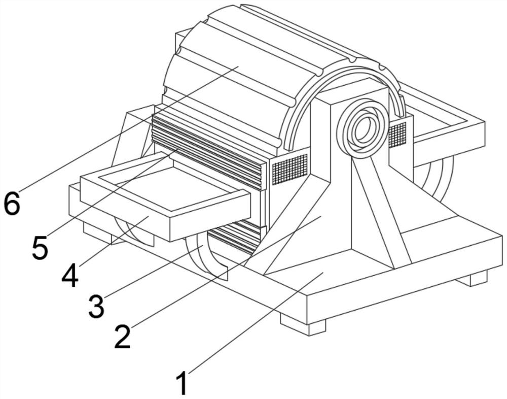
[0040] see Figure 1-6 , the present invention provides a technical solution: a solar cell silicon wafer drying equipment, including a fixed base 1, a drying device 6 is fixedly connected to the middle position of the top of the fixed base 1, and the middle part of the outer wall on both sides of the drying device 6 is provided with The opening and closing baffle 5, the middle part of the side of the opening and closing baffle 5 away from the drying device 6 is provided with a conveying line 4, both sides of the bottom of the conveying line 4 are fixedly connected with arc-shaped brackets 3, and the top of the fixed base 1 is located at the drying Both sides of the device 6 are fixedly connected with connecting support plates 2 .

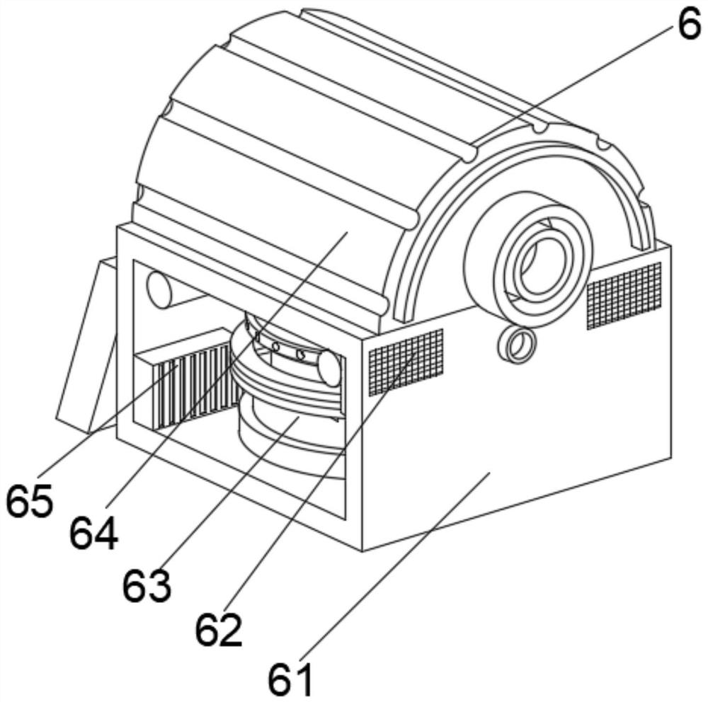
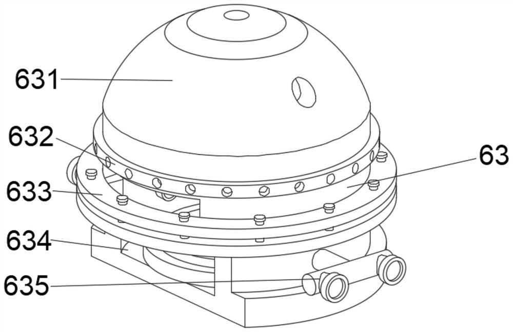
[0041] Wherein, the drying device 6 includes a drying box 61, the top of the drying box 61 is fixedly connected with an auxiliary mechanism 64, the top of the right side outer wall of the drying box 61 is provided with a ventilating plate (62), and ...

Embodiment 2

[0047] see Figure 1-6 , on the basis of Embodiment 1, the present invention provides a technical solution: a method for using solar cell silicon wafer drying equipment, which is characterized in that: Step 1: Place the equipment in a stable position, and connect the conveying line 4 with the The assembly line for cell production is connected, and the equipment is started, so that when the cells placed on the surface of the conveying line 4 touch the sensor, the opening and closing baffle shrinks to create a space for entry and exit, and the conveying line extends to the inside of the drying device 6;

[0048] Step 2: The cells are dried, the internal temperature is increased, the vacuum valve 65 and the air-permeable plate (62) control the internal vacuum, and the middle part of the drying mechanism 63 can be separated when entering the cell for drying, realizing Drying of the front and back of the cell;

[0049] Step 3: After receiving the signal of battery entry, the clamp...


PUM


Abstract

The invention discloses solar cell silicon wafer drying equipment which comprises a fixed base, a drying device is fixedly connected to the middle of the top of the fixed base, opening and closing baffles are arranged in the middles of the outer walls of the two sides of the drying device, and a conveying line is arranged in the middle of the side, away from the drying device, of each opening and closing baffle. Arc-shaped supports are fixedly connected to the two sides of the bottom of the conveying line, and connecting supporting plates are fixedly connected to the positions, located on the two sides of the drying device, of the top of the fixed base. According to the solar cell silicon wafer drying equipment, the conveying line and the clamping baffles guarantee the position accuracy and the internal sealing performance of the cell pieces, workers are not prone to making contact with the equipment, the situation that the workers are scalded by high temperature on the surface of the equipment is avoided, meanwhile, the drying mechanism is tightly matched with the auxiliary mechanism, the drying time is shortened, and the drying efficiency is improved. And the phenomenon that the stacked battery pieces are broken due to uneven stress caused by the fact that the positions of the dried battery pieces move is prevented.

Description

technical field [0001] The invention relates to the technical field of solar cells, in particular to a solar cell silicon wafer drying equipment. Background technique [0002] Solar cells mainly include crystalline silicon cells and thin film cells. Their respective characteristics determine that they have irreplaceable positions in different applications. In crystalline silicon solar power generation systems, one of the core steps to realize photoelectric conversion is to convert the crystal The process of processing silicon into cells that realize photoelectric conversion, so the photoelectric conversion efficiency of cells has become a key indicator that reflects the technical level of crystalline silicon solar power generation systems. [0003] According to Chinese Patent No. CN111540809A, a solar cell silicon wafer drying and curing integrated equipment realizes the loading of silicon wafers to the carrier board on the feeding transmission line, and the feeding and feed...

Claims


Application Information

Patent Timeline
Patent Type & Authority Applications(China)
IPC IPC(8): F26B9/06F26B21/00F26B25/00
CPCF26B9/066F26B21/001F26B21/004F26B25/003F26B25/007
Inventor 马明阳
Owner 馬明陽
Learn More