
Plunger valve for high-frequency switch working condition

A high-frequency switch and plunger valve technology, used in valve devices, valve details, sliding valves, etc., can solve the problems of poor sealing between the plunger and the valve seat, poor reliability, easy erosion, etc., and achieve good sealing reliability. , good sealing stability, good guiding rigidity

Pending Publication Date: 2022-04-26
WUXI SMART AUTO CONTROL ENG CO LTD
View PDF0 Cites 0 Cited by
  • Summary
  • Abstract
  • Description
  • Claims
  • Application Information

AI Technical Summary

Problems solved by technology

Because the medium is easy to block, easy to erode, flammable, explosive, toxic, etc., and the valve switching time needs to be less than 3 seconds, the action is frequent, and the sealing level requires level VI, so the operating conditions of the valve are extremely strict
Traditional plunger valves generally have disadvantages such as easy material blockage, inconvenient maintenance, fast and high-frequency switching action, poor reliability, poor sealing between the plunger and valve seat, and easy leakage of packing, which seriously affects the safety, continuous and stable operation of the device.

Method used


Image

  • Plunger valve for high-frequency switch working condition
  • Plunger valve for high-frequency switch working condition
  • Plunger valve for high-frequency switch working condition

Examples


Embodiment Construction

[0033] The specific embodiments of the present invention will be further described below in conjunction with the accompanying drawings.

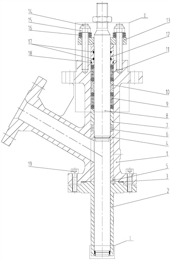
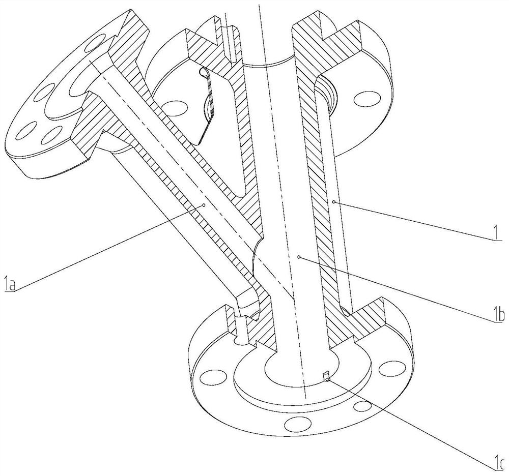
[0034] Such as Figure 1~6 As shown, the present invention is a plunger valve for high-frequency switching conditions, including a valve seat 2, the valve seat 2 is in sealing connection with the valve body 1, and the valve body 1 is provided with a valve body side pipe flow channel 1a. In practice, In order to effectively prevent the medium from sticking and facilitate the flow of the medium, the surface roughness of the valve body side pipe flow channel 1a is ≤Ra0.4μm.

[0035] The inner cavity 1b of the valve body is provided with a bushing 4, and the side of the bushing 4 is provided with a bushing window 4c, and the bushing window 4c communicates with the side pipe flow channel 1a of the valve body.

[0036] Corresponding to the upper end of the bushing 4, the inner cavity 1b of the valve is provided with a sealing ring 6, a guide slee...


PUM


Abstract

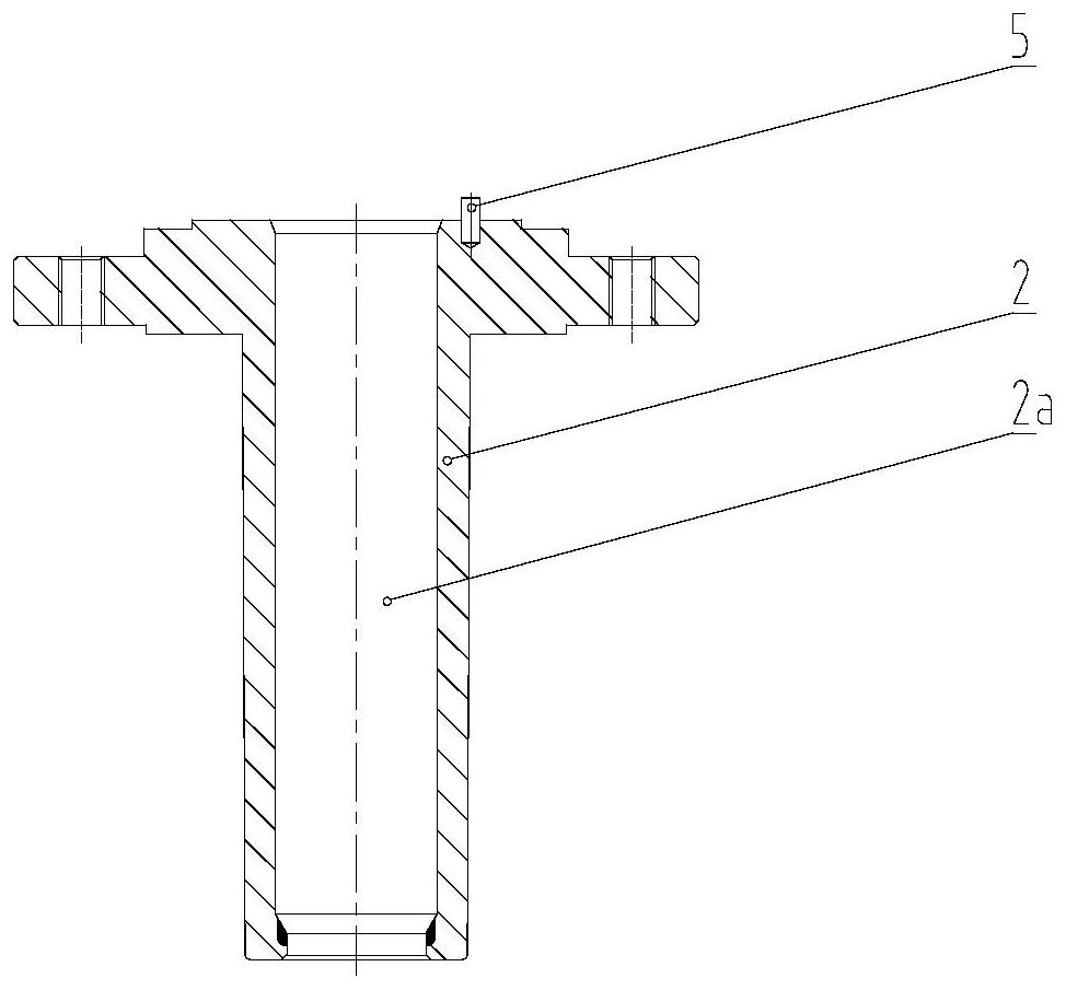
The invention belongs to the technical field of fluid control valves, and relates to a plunger valve for a high-frequency switch working condition, which comprises a valve seat, the valve seat is hermetically connected with a valve body, the valve body is provided with a valve body side pipe runner, a bushing is arranged in an inner cavity of the valve body, a bushing window is arranged on the side part of the bushing, and the bushing window is communicated with the valve body side pipe runner; a sealing ring, a guide sleeve, a first packing set, a packing spacer bush, a second packing set and a packing gland are sequentially arranged at the position, corresponding to the upper end of the lining, of an inner cavity of the valve body, the lower portion of the packing gland is arranged in an inner hole of the valve body, the upper end of the packing gland is axially limited through a pressing plate assembly, and a plunger is arranged in an inner hole of the lining and an inner hole of the valve seat. An inner hole of the packing gland is in sealing fit with the plunger, and the packing gland is in sealing fit with the valve body. The plunger valve has the advantages of being not prone to material blocking, convenient to disassemble and assemble, rapid, good in high-frequency switching action reliability, high in plunger and valve seat sealing grade, capable of meeting the low-dissipation emission requirement of filler and the like.

Description

technical field [0001] The invention belongs to the technical field of fluid control valves, and relates to a plunger valve for high-frequency switching conditions. Background technique [0002] Polypropylene (referred to as PP) is a colorless, translucent thermoplastic lightweight general-purpose plastic with excellent performance. It has good chemical resistance, heat resistance, electrical insulation, high strength toughness and high wear resistance, and is widely used In machinery, automobile, electronics, textile, packaging, food, pharmaceutical and other industries. Polypropylene is a polymer produced by addition polymerization of propylene. Its production methods mainly include slurry method, solution method, bulk method, gas phase method, etc., among which bulk method and gas phase method are dominant. [0003] Plunger valves are widely used in polypropylene production equipment. They are mainly used for program control of the bottom or top inlet and outlet of vario...

Claims


Application Information

Patent Timeline
IPC IPC(8): F16K3/24F16K41/02F16K27/04F16K25/00
CPCF16K3/246F16K3/243F16K41/02F16K27/041F16K25/005
Inventor 张志超张程信王汪洋张瀚霆
Owner WUXI SMART AUTO CONTROL ENG CO LTD
Learn More