Multi-new-energy utilization complex for farmland irrigation area

A technology for farmland irrigation and new energy, which is applied in a variety of new energy utilization complexes. It can solve the problems of insufficient battery power, inability to fully utilize wind energy, and failure to drive water pumps, etc., to achieve the effect of ensuring power generation efficiency.

Pending Publication Date: 2022-04-29
HARBIN ENG UNIV
View PDF4 Cites 0 Cited by
  • Summary
  • Abstract
  • Description
  • Claims
  • Application Information

AI Technical Summary

Problems solved by technology

The whole system does not have a power generation and energy storage device. When the wind and light conditions are not good, the system may not be able to drive the pump to work.
For the patent application number 201520207239.6, the name is "a farmland irrigation equipment based on wind power". The irrigation equipment uses many electronic equipment, such as humidity sensors, water level sensors, water pumps, solenoid valves, control panels, and the equipment is powered by wind turbines. To provide electricity, when there is continuous weak wind, the battery may have insufficient power, and it cannot fully utilize wind energy to operate independently

Method used


Image

  • Multi-new-energy utilization complex for farmland irrigation area
  • Multi-new-energy utilization complex for farmland irrigation area
  • Multi-new-energy utilization complex for farmland irrigation area

Examples


Embodiment 1

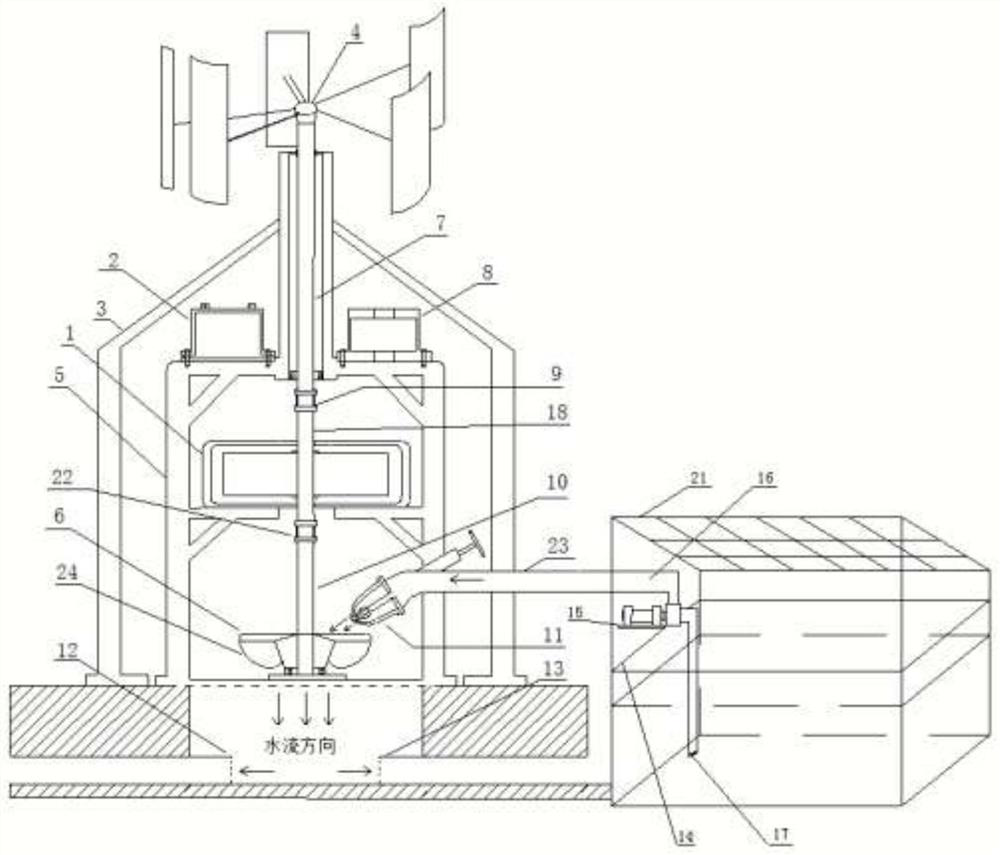
[0029] refer to Figure 1 The invention provides a multi-new energy utilization complex for farmland irrigation areas, which comprises a machine room 3, a wind power mechanism is arranged at the top of the machine room 3, a tower 5 is arranged in the machine room 3, a generator 1 is arranged in the tower 5, a generator shaft 18 is fixedly connected in the generator 1, two ends of the generator shaft 18 extend out of the generator 1, the generator shaft 18 is fixedly connected with the wind power mechanism, and a hydro-power generation mechanism is arranged at the bottom of the tower 5, which is fixedly connected with the generator shaft 18. The top of the tower 5 is fixedly connected with a power storage mechanism, which is electrically connected with the generator 1; one side of the machine room 3 is provided with a water storage mechanism, which extends into the machine room 3; the top of the water storage mechanism is provided with a photovoltaic mechanism, which is electrically...

Embodiment 2

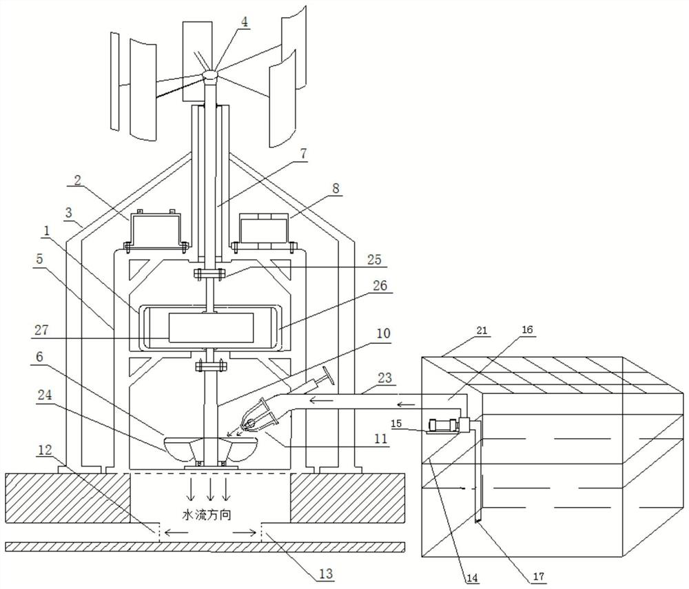
[0044] refer to Figure 2 The difference from the first embodiment is that the generator 1 is composed of a rotor assembly 27 and a stator assembly 26, both of which can rotate. The rotor assembly 27 of the generator 1 is connected with the wind turbine main shaft 7 through a flange 25, and a bearing is installed in the middle of the tower 5 to support and fix the wind turbine main shaft 7. The stator assembly 26 is connected with the turbine main shaft 10, which fixes the rotation direction of the wind turbine 4 to the opposite direction to that of the turbine 6. Under the condition of sufficient wind power, wind power can drive the wind turbine 4 to rotate, drive the generator rotor assembly 27 to rotate, and make the generator 1 generate electricity; The farmland irrigation water is used to impact the blades of the water turbine to drive the generator stator assembly 26 to rotate, and the generator 1 can also generate electricity. When both of them work at the same time, the rot...

Embodiment 3

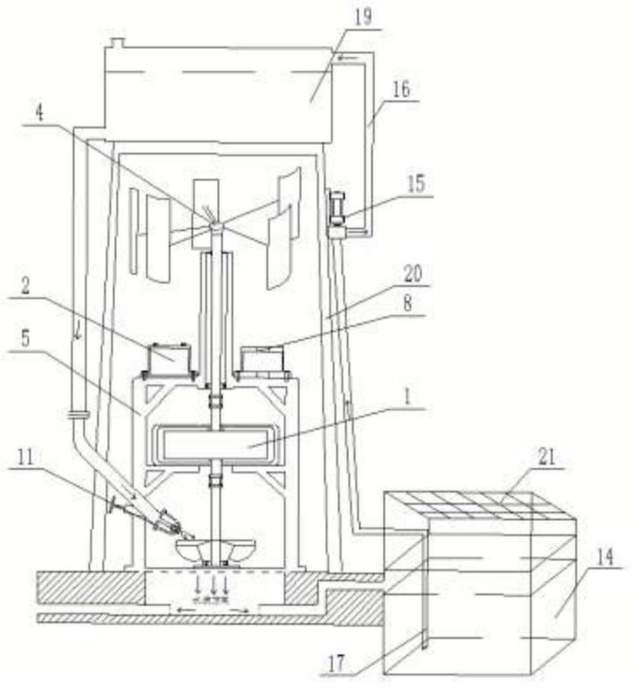
[0046] Different from Examples 1 and 2, the reference Figure 3-4 A grid frame 20 is installed outside the tower 5, the wind turbine 4 is located in the grid frame 20, the photovoltaic water pump 15 is installed on the side wall of the grid frame 20, the top of the grid frame 20 is fixedly connected with a high-level reservoir 19, and the photovoltaic water pump 15 is respectively communicated with the reservoir 14 and the high-level reservoir 19 through a water pump inlet pipe 17 and a water pump outlet pipe 16, and one end of the high-level reservoir 19 far from the water pump outlet pipe 16 is provided with a water outlet which is connected with a nozzle 11 through a connecting pipe.

[0047] Under the sunny weather conditions, the photovoltaic panel 21 outputs electric energy to drive the photovoltaic water pump 15 to work, pumping the water in the reservoir 14 into the high-level reservoir 19, and the water in the high-level reservoir 19 is transported by the connecting pipe t...


PUM


Abstract

The invention discloses a multi-new energy utilization complex for farmland irrigation areas, which comprises a machine room, a wind power mechanism arranged at the top of the machine room, a tower arranged in the machine room, a generator arranged in the tower, a generator rotating shaft fixedly connected in the generator, two ends of the generator rotating shaft extending out of the generator, and the generator rotating shaft fixedly connected with the wind power mechanism. A hydroelectric generation mechanism is arranged at the bottom of the tower and fixedly connected with a rotating shaft of the generator, an electricity storage mechanism is fixedly connected to the top of the tower and electrically connected with the generator, a water storage mechanism is arranged on one side of the machine room and extends into the machine room, and a photovoltaic mechanism is arranged at the top of the water storage mechanism and electrically connected with the electricity storage mechanism. According to the invention, the condition that no overhigh building shields sunlight and wind power in a large-area farmland area is fully utilized, wind-solar complementary power generation is realized, and power generation can be realized under any weather condition.

Description

Technical field [0001] The invention relates to the field of farmland irrigation and power generation, in particular to a new energy utilization complex for farmland irrigation areas. technical background [0002] With the rapid development of productivity, the energy consumption is also increasing, among which the consumption of oil and coal accounts for a great proportion. However, with the gradual warming of the global climate in recent years and the depletion of oil resources, the development of new energy is extremely urgent. In recent years, hydropower technology has developed rapidly. Water-rich areas in China are almost covered with large and small hydropower devices, and hydropower is a clean energy source. Therefore, China attaches great importance to hydropower, and the unit capacity of large-scale power stations continues to become giant. At the same time, with the economic development and the increasing shortage of energy, small hydropower will develop rapidly. In ma...

Claims


Application Information

Patent Timeline
Patent Type & Authority Applications(China)
IPC IPC(8): F03D9/11F03D9/45F03D15/20F03B13/06H02K7/10H02K7/18H02S10/10H02S10/20
CPCF03D9/007F03D9/008F03D9/11F03D9/45F03D15/20F03B13/06H02K7/10H02K7/183H02K7/1823H02S10/10H02S10/20Y02E10/20Y02E10/50Y02E10/72Y02E10/728Y02E60/16Y02E70/30Y02B10/30
Inventor 程鹏徐智禹李睿烨潘韬毛哲浩郭泽芸胡涛李大鹏李昊任艺格肖培轩
Owner HARBIN ENG UNIV
Why Eureka
Try Eureka