Wind power hollow main shaft inner hole extruding and expanding forming process

A technology of hollow spindle and forming process, which is applied in the direction of manufacturing tools, piercing presses, metal processing equipment, etc., and can solve the problems of difficult repair, waste of raw materials, and large forming force

Pending Publication Date: 2022-05-06
TONGYU HEAVY IND
View PDF16 Cites 0 Cited by
  • Summary
  • Abstract
  • Description
  • Claims
  • Application Information

AI Technical Summary

Problems solved by technology

[0003] 1. The elongation of the upper flat and lower V anvil belongs to a kind of asymmetric deformation up and down, which will cause uneven metal flow. When the forging is elongated, the amount of pressing down each time cannot be exactly the same, and the overlap between every two forgings is also It is impossible to keep consistent, resulting in uneven wall thickness after elongation, which brings difficulties to machining
Due to the uneven feeding, the two ends of the drawing are not neat, so it is necessary to use sawing or gas cutting to process the blank, which wastes raw materials and prolongs the production cycle.
[0004] 2. In order to solve the problem of uneven wall thickness and length, it is necessary to increase the forging allowance, and then remove the allowance by machining to complete the forging, which will not only waste a lot of raw materials, but also increase the production cycle and reduce

Method used


Image

  • Wind power hollow main shaft inner hole extruding and expanding forming process
  • Wind power hollow main shaft inner hole extruding and expanding forming process
  • Wind power hollow main shaft inner hole extruding and expanding forming process

Examples


Embodiment 1

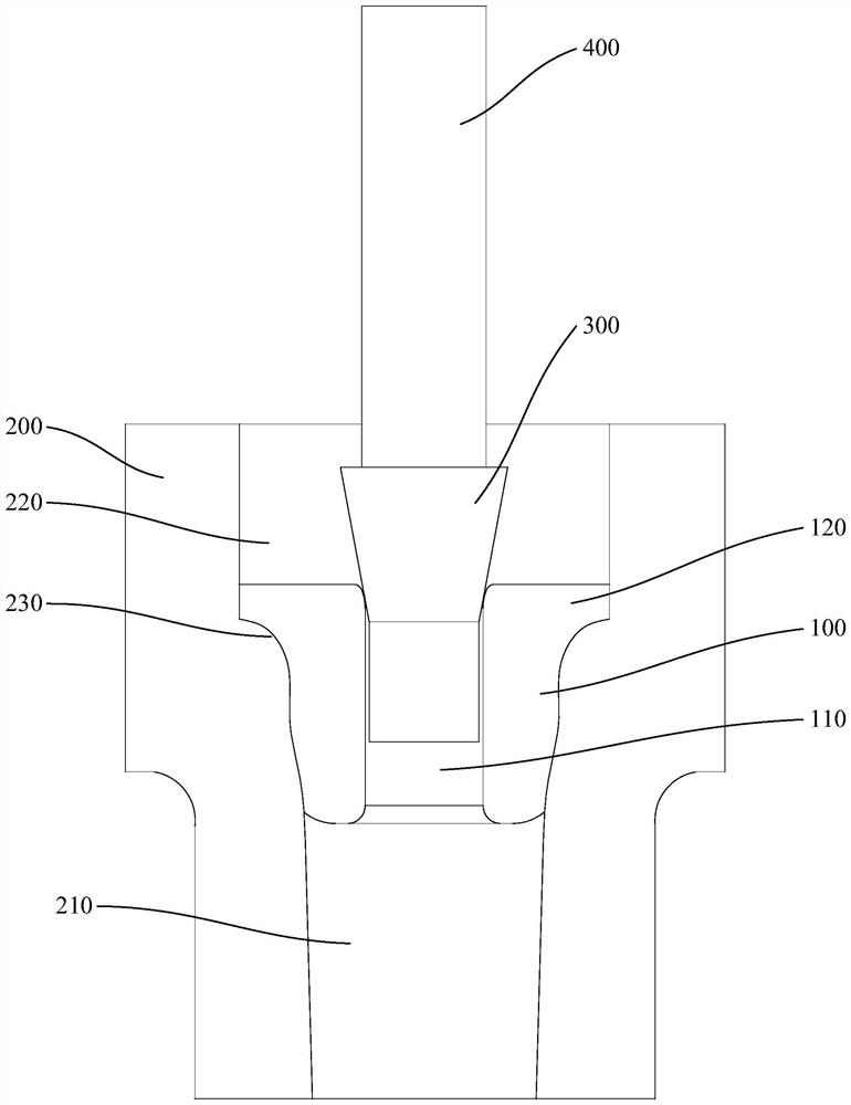
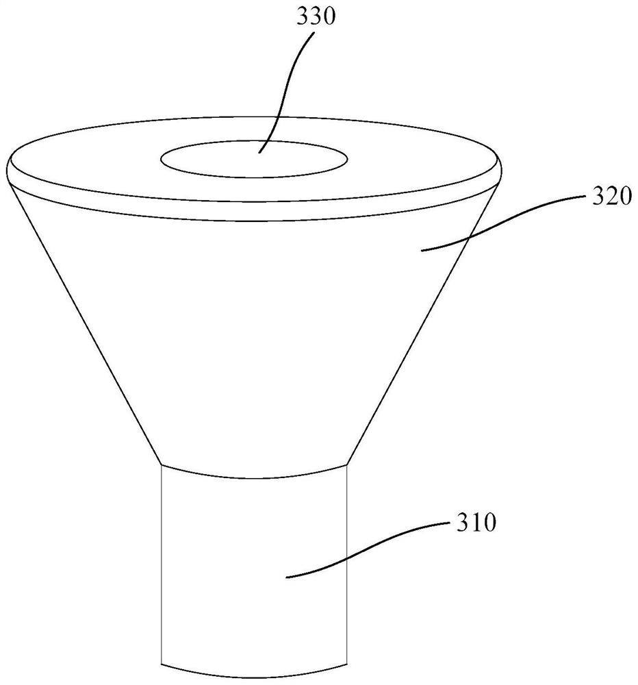
[0051] Prepare a 3MW wind power hollow main shaft, the diameter of the through hole 110 of the blank 100 is 460 mm, the length of the guide slope 130 is 210 mm, the diameter of the guide part 310 of the extruding tool 300 is 450 mm, the The obtuse angle formed by the side surface of the extruded part 320 and the side surface of the guide part 310 is 155°, and the length of the side surface of the extruded part 320 is 600 mm. Lubricant is applied on the inner surface of the forming die 200 and the outer surface of the extruding tool 300 .

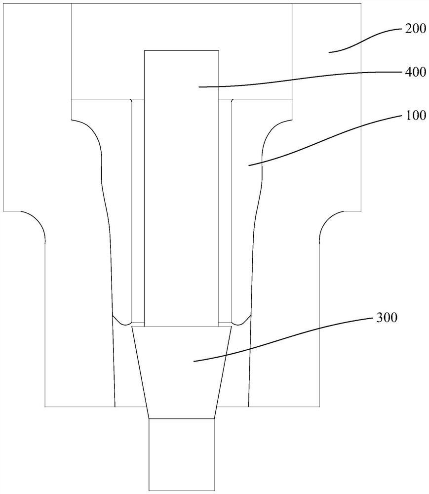
[0052] Heat the blank 100 to above 1220°C, put the blank 100 into the forming mold 200, match the flange end 120 of the blank 100 with the positioning groove 220, and place the extrusion The expanding tooling 300 is inserted into the through hole 110 of the flange end 120, and then the connecting part 410 of the extruding tooling 400 is connected with the connecting hole 330 of the extruding tooling 300 . Use an extruder to press down the ...

Embodiment 2

[0054] Prepare a 3MW wind power hollow main shaft, the diameter of the through hole 110 of the blank 100 is 480mm, the length of the guide slope 130 is 220mm, the diameter of the guide part 310 of the extruding tool 300 is 475mm, the The obtuse angle formed by the side surface of the extruded part 320 and the side surface of the guide part 310 is 145°, and the length of the side surface of the extruded part 320 is 600 mm. Lubricant is applied on the inner surface of the forming die 200 and the outer surface of the extruding tool 300 .

[0055] Heat the blank 100 to above 1220°C, put the blank 100 into the forming mold 200, match the flange end 120 of the blank 100 with the positioning groove 220, and place the extrusion The expanding tooling 300 is inserted into the through hole 110 of the flange end 120, and then the connecting part 410 of the extruding tooling 400 is connected with the connecting hole 330 of the extruding tooling 300 . Use an extruder to press down the ext...

Embodiment 3

[0057] Prepare a 3MW wind power hollow main shaft, the diameter of the through hole 110 of the blank 100 is 470 mm, the length of the guide slope 130 is 200 mm, the diameter of the guide part 310 of the extrusion tooling 300 is 460 mm, the The obtuse angle formed by the side surface of the extruded part 320 and the side surface of the guide part 310 is 155°, and the length of the side surface of the extruded part 320 is 600 mm. Lubricant is applied on the inner surface of the forming die 200 and the outer surface of the extruding tool 300 .

[0058] Heat the blank 100 to above 1220°C, put the blank 100 into the forming mold 200, match the flange end 120 of the blank 100 with the positioning groove 220, and place the extrusion The expanding tooling 300 is inserted into the through hole 110 of the flange end 120, and then the connecting part 410 of the extruding tooling 400 is connected with the connecting hole 330 of the extruding tooling 300 . Use an extruder to press down t...


PUM


Abstract

The invention provides a wind power hollow main shaft inner hole extruding and expanding forming process, and particularly relates to the field of large wind power main shaft manufacturing, which comprises the following steps: providing a blank, heating the blank to 1220 DEG C or above, then putting the blank into a forming die, inserting an extruding and expanding tool into the blank, then connecting one end of an extruding rod with the extruding and expanding tool, and then extruding and expanding the extruding rod into the forming die; and an extruding machine is used for pressing down the extruding rod, and after inner hole extruding and expanding are completed, the extruding rod is separated from the extruding and expanding tool and then taken out. According to the extrusion-expansion forming process for the inner hole of the wind power hollow main shaft, the forming die, the extrusion-expansion tool and the extrusion rod are used for conducting one-time extrusion-expansion forming on the blank, the needed extrusion-expansion forming force is small, the forming speed is high, the forging allowance is small, the production rate of a product can be effectively increased, the loss of raw materials of the product is reduced, and the production cost is reduced. And the working intensity of workers is reduced.

Description

technical field [0001] The invention relates to the field of manufacturing large-scale wind power main shafts, in particular to an extrusion and expansion forming process for the inner hole of a wind power hollow main shaft. Background technique [0002] With the development of wind power technology, the wind power main shaft has a trend of large-scale and lightweight development. The size of the inner hole of the wind power main shaft continues to increase. When the diameter of the inner hole of the wind power main shaft is greater than 400mm, the hollow forging process is generally adopted. Hollow forging process Generally, after punching, insert the mandrel, and use the upper flat and lower V anvil to pull out the length. The process has the following problems: [0003] 1. The elongation of the upper flat and lower V anvil belongs to a kind of asymmetric deformation up and down, which will cause uneven metal flow. When the forging is elongated, the amount of pressing dow...

Claims


Application Information

Patent Timeline
IPC IPC(8): B21K1/06B21J5/02B21J5/10B21J9/04B21J13/02B21J13/08
CPCB21K1/063B21J5/025B21J5/10B21J9/04B21J13/02B21J13/085
Inventor 张帅李威李国瑞白云欣贾聪香
Owner TONGYU HEAVY IND
Why Eureka
Try Eureka