Die-cutting machine capable of preventing poor sleeve position caused by electrostatic adsorption of materials to machine

An electrostatic adsorption and die-cutting machine technology, applied in the direction of static electricity, dryers, electrical components, etc., can solve the problems of inaccurate cutting, affecting production efficiency, and damaging materials, so as to accelerate charge leakage, reduce defective products, and facilitate The effect of using

Pending Publication Date: 2022-05-06
苏州鼎佳精密科技股份有限公司
View PDF0 Cites 0 Cited by
  • Summary
  • Abstract
  • Description
  • Claims
  • Application Information

AI Technical Summary

Problems solved by technology

[0004] At present, in the actual production and application of die-cutting machines, due to factors such as transmission friction and air drying of die-cutting materials, this will cause static electricity on the surface of the material, which will make the material become adsorbent and move closer to the machine, thus making the material and the cutter The position of the machine is offset, resulting in inaccurate cutting, damage to the material, and affecting production efficiency

Method used


Image

  • Die-cutting machine capable of preventing poor sleeve position caused by electrostatic adsorption of materials to machine
  • Die-cutting machine capable of preventing poor sleeve position caused by electrostatic adsorption of materials to machine
  • Die-cutting machine capable of preventing poor sleeve position caused by electrostatic adsorption of materials to machine

Examples


Embodiment Construction

[0026] The following will clearly and completely describe the technical solutions in the embodiments of the present invention with reference to the accompanying drawings in the embodiments of the present invention. Obviously, the described embodiments are only some, not all, embodiments of the present invention. The specific embodiments described here are only used to explain the present invention, not to limit the present invention. Based on the embodiments of the present invention, all other embodiments obtained by persons of ordinary skill in the art without making creative efforts belong to the protection scope of the present invention.

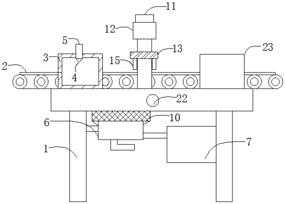
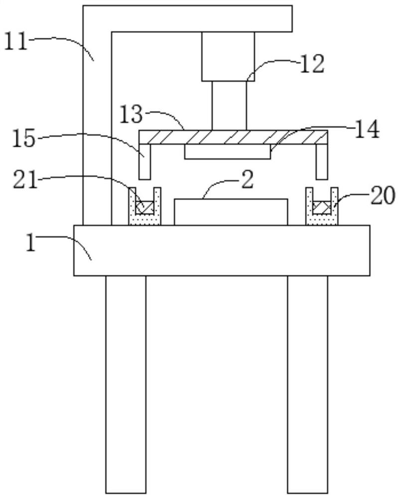
[0027] The present invention provides such Figure 1-5 A die-cutting machine shown to prevent poor positioning due to electrostatic adsorption of materials, including a workbench 1, which is used to support and fix the entire device. The table of the workbench 1 is respectively equipped with a feeding belt 2, a spray box 3 and a drying ma...


PUM


Abstract

The invention discloses a die-cutting machine capable of preventing poor nesting caused by electrostatic adsorption of materials to the machine, and belongs to the technical field of die-cutting machines. The die-cutting machine comprises a workbench, a feeding belt, a spraying box and a drying box are installed on the table top of the workbench, an air pump seat is welded to the bottom of the workbench, an air pump is installed on one side of the air pump seat, and a motor is installed on the other side of the air pump seat; an air inlet pipe is welded to the output end of the air pump, a spraying head is installed at one end of the air inlet pipe, the input end of the air pump is inserted into one side of a water tank, an ultrasonic nebulizer is installed in the water tank, a supporting frame is welded to the table top of the workbench, and an electric push rod is installed on one side of the supporting frame. A supporting plate is welded to the output end of the electric push rod. The static electricity removing device is simple in structure and high in practicability, static electricity can be effectively removed when a material is subjected to die cutting, meanwhile, an alarm is given out in time when positioning is inaccurate, and the number of defective products can be greatly reduced.

Description

technical field [0001] The invention belongs to the technical field of die-cutting machines, and in particular relates to a die-cutting machine for preventing poor positioning due to electrostatic adsorption of materials. Background technique [0002] Die-cutting machine is also called beer machine, cutting machine, CNC stamping machine, mainly used for die-cutting of some corresponding non-metallic materials, self-adhesive, EVA, double-sided adhesive, electronics, mobile phone rubber pad, etc. breaking), indentation and bronzing operations, lamination, automatic waste discharge, die-cutting machines use steel knives, metal molds, steel wires (or templates carved from steel plates), and apply a certain pressure through the embossing plate to print or The cardboard is rolled and cut into certain shapes. It is an important equipment for post-press packaging processing and molding. [0003] The working principle of the die-cutting machine is to use a die-cutting knife, a stee...

Claims


Application Information

Patent Timeline
IPC IPC(8): B26F1/40B26D7/00B26D7/27H05F3/00F26B23/06F26B21/00
CPCB26F1/40B26D7/00B26D7/27H05F3/00F26B23/06F26B21/001
Inventor 李结平
Owner 苏州鼎佳精密科技股份有限公司
Why Eureka
Try Eureka