
Air turbine rocket stamping combined propulsion system

An air turbine and propulsion system technology, applied in the field of aerospace propulsion systems, can solve the problems of restricting flight mission closure, difficult engine matching, insufficient thrust, etc., and achieve the effects of widening the working flight Mach number, increasing the working range, and solving the insufficient thrust

Active Publication Date: 2022-05-06
NORTHWESTERN POLYTECHNICAL UNIV
View PDF12 Cites 2 Cited by
  • Summary
  • Abstract
  • Description
  • Claims
  • Application Information

AI Technical Summary

Problems solved by technology

Two kinds of engines work in different modes, the working speed range of components is wide, the working environment changes greatly, and the compatibility of components is high, which puts forward high requirements for the design of the engine. The existing turbine-based combined engine is in the rotating mode Sometimes there is a problem of insufficient thrust, or relatively weak performance, etc., but the traditional engine adopts a fixed geometry method, and it is difficult to match the engine. In this way, the working speed range and range of the engine are relatively small, which is suitable for wide speed range and The flight process in a large airspace creates great constraints, and at the same time restricts the closure of the flight mission

Method used


Image

  • Air turbine rocket stamping combined propulsion system
  • Air turbine rocket stamping combined propulsion system
  • Air turbine rocket stamping combined propulsion system

Examples


Embodiment 1

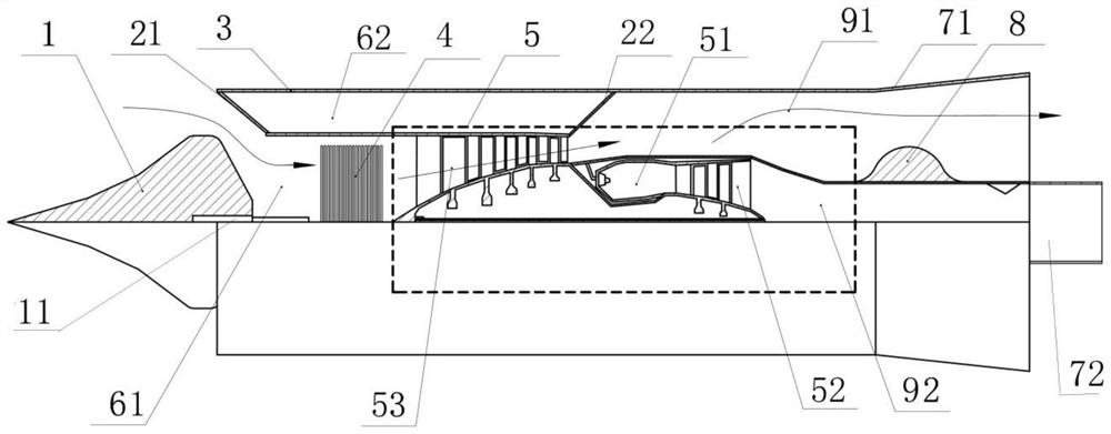
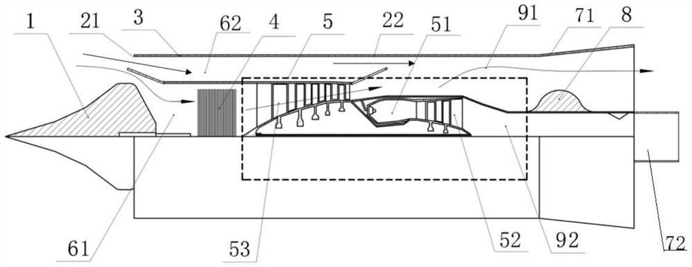
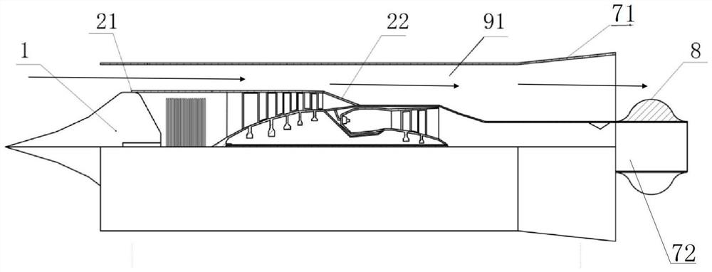
[0046] Embodiment 1: an air turbine rocket ramjet combined propulsion system, comprising a core machine 5 of an air turbine rocket engine, and the core machine 5 includes a coaxially arranged rocket gas generator 51, a turbine 52 and a compressor 53;

[0047] The core machine 5 is arranged in the central flow channel 61 of the air turbine rocket, the core machine 5 is provided with a casing 3 on the periphery, and a stamping isolation section flow channel 62 is arranged in the casing 3, and the stamping isolation section flows. The front end of the channel 62 is provided with a first mode conversion valve 21 corresponding to the inlet of the central flow channel 61, and the end of the flow channel 62 in the stamping isolation section is provided with a second mode conversion valve 22 corresponding to the outlet of the compressor 53; The rocket gas generator 51 is arranged behind the compressor 53, and the periphery of the rocket gas generator 51 is provided with a first combust...


PUM


Abstract

The invention relates to an air turbine rocket ramjet combined propulsion system which comprises a core engine of an air turbine rocket engine, the core engine is arranged in a central flow channel of an air turbine rocket, a cartridge receiver is arranged on the periphery of the core engine, and a ramjet isolation section flow channel is arranged in the cartridge receiver. A first mode conversion valve is arranged at the front end, corresponding to an inlet of the central runner, of the stamping isolation section runner, and a second mode conversion valve is arranged at the tail end, corresponding to an outlet of the gas compressor, of the stamping isolation section runner; a first combustion chamber is arranged behind the second mode conversion valve; a turbine outlet of the core machine is provided with a second combustion chamber, and the outer wall of the second combustion chamber is provided with an adjustable throat used for guaranteeing the combustion state of the engine; by means of the series connection mode, the ATR and the scramjet engine are organically combined together, the performance of the combined engine in the rotating mode is improved, the flight speed range of the engine is widened, and the performance of the engine in each mode is enhanced.

Description

technical field [0001] The invention relates to an aerospace propulsion system, in particular to a turbo rocket stamping combined propulsion system. Background technique [0002] The mission requirements of the aircraft are becoming more and more complex, and the requirements for the propulsion system of the aircraft are becoming more and more stringent. The engine must work on the flight profile of large airspace, high speed and wide speed range to achieve the goal of fast, economical and repeatable use. . One of the ways to improve the wide speed range of the combined engine is to organically combine two engines with a wide speed range. At the same time, the working ranges of the two engines have a large overlapping part, and the performance of the two engines is relatively high in the overlapping part. high. Due to the complexity of the flight mission, the engine requires a high thrust-to-weight ratio, low fuel consumption, high thrust, simple structure, zero-speed take...

Claims


Application Information

Patent Timeline
Patent Type & Authority Applications(China)
IPC IPC(8): F02K7/18F02K7/16
CPCF02K7/18F02K7/16
Inventor 杜金峰史新兴陈玉春
Owner NORTHWESTERN POLYTECHNICAL UNIV
Learn More