Hydraulic circuit including hydraulic pressure reduction energy recovery

A hydraulic circuit and hydraulic fluid technology, which is applied in the field of hydraulic circuits including hydraulic decompression energy recovery, can solve problems such as wasting energy and reducing pressure

Pending Publication Date: 2022-05-06
ROBERT BOSCH GMBH
View PDF0 Cites 0 Cited by
  • Summary
  • Abstract
  • Description
  • Claims
  • Application Information

AI Technical Summary

Problems solved by technology

In some conventional hydraulic circuits, excess fluid is vented into a reservoir to reduce pressure, essentially wasting energy and generating heat

Method used


Image

  • Hydraulic circuit including hydraulic pressure reduction energy recovery
  • Hydraulic circuit including hydraulic pressure reduction energy recovery
  • Hydraulic circuit including hydraulic pressure reduction energy recovery

Examples


Embodiment Construction

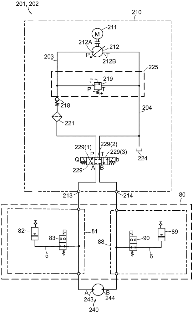
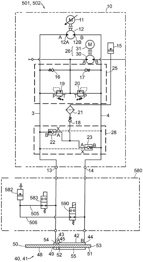
[0042] refer to figure 1 , The oscillating hydraulic system 1 includes a hydraulic circuit 2 . The hydraulic circuit 2 includes an actuator 40 that performs work and a prime mover 10 that controls the flow of hydraulic fluid to the actuator 40 . As used herein, the term "hydraulic fluid" refers to the fluid within the hydraulic circuit 2 . In the illustrated embodiment, the hydraulic fluid is oil, but is not limited thereto. The hydraulic circuit 2 also includes a recovery device 80 disposed between the prime mover 10 and the actuator 40 in the hydraulic circuit 2 . The recovery device 80 allows the oscillating hydraulic system 1 to avoid hydraulic locking by allowing the high pressure side of the actuator to decompress immediately before the actuation direction is reversed. Additionally, recovery device 80 allows the hydraulic system to capture (recover) decompression energy for subsequent use by the hydraulic system, as discussed in detail below.

[0043] Prime mover 10 ...


PUM


Abstract

The invention relates to a hydraulic circuit including hydraulic reduced pressure energy recovery. A hydraulic circuit includes a prime mover configured to generate an oscillatory flow of hydraulic fluid and an actuator driven by the prime mover and configured to provide an oscillatory motion and connected to a load in each direction of the motion. The hydraulic circuit also includes a recovery device disposed in the hydraulic circuit between the prime mover and the actuator. The recovery device captures and stores a portion of the hydraulic fluid displaced from the actuator during a transition between the opposite movements, where the portion of the hydraulic fluid corresponds to an amount of the hydraulic fluid, that is, the amount of hydraulic fluid is equal to the volume of fluid required to compensate for fluid compression within the hydraulic circuit due to system pressure and load pressure. The stored fluid is used by the circuit in subsequent motion.

Description

Background technique [0001] Hydraulic circuits enable the transmission and control of power or signals through fluids, especially liquids, and are used in industrial and mobile applications to transmit power from prime movers to operate machine components or vehicles. A hydraulic circuit consists of several components such as: a prime mover configured to supply pressurized hydraulic fluid to an actuator that converts fluid pressure into mechanical force; and Auxiliary components such as valves, filters, etc. [0002] Because fluids are compressible, the minimum pressure P must be increased min The volume V of the fluid under min , in order to fill the higher pressure P s The system volume under V system . The extra volume is referred to herein as "additional compression volume" V c , thus at pressure P min The volume V of the fluid drawn from the reservoir under min is compressed to a higher pressure P s : [0003] V min = V system +V c [0004] The fluid conta...

Claims


Application Information

Patent Timeline
IPC IPC(8): F15B1/04F15B11/08F15B13/02F15B20/00F15B21/00
CPCF15B1/04F15B11/08F15B13/02F15B20/00F15B21/008F15B21/14F15B2211/88F15B1/024F15B7/006F15B2211/20561F15B2211/20515F15B2211/20576F15B2211/20584F15B2211/212F15B15/12F15B2211/7058F15B7/008F15B2211/7054F15B7/10F15B1/033F15B2211/27F15B2211/7128F15B2211/613F15B2211/611F15B2211/625F15B2211/615F15B2211/50527F15B2211/41572F15B2211/50518F15B2211/5157F15B2211/20546F15B2211/6651F15B2201/413F15B2201/411F15B21/006
Inventor R·格恩格罗斯J·迪尔O·格哈德R·克内尔
Owner ROBERT BOSCH GMBH
Why Eureka
Try Eureka