Coherent lidar

A laser radar and laser technology, applied in the field of optics, can solve problems such as interference signal drop

Pending Publication Date: 2022-05-06
SUZHOU LEIZHI SENSOR TECH CO LTD
View PDF0 Cites 2 Cited by
  • Summary
  • Abstract
  • Description
  • Claims
  • Application Information

AI Technical Summary

Problems solved by technology

[0005] The invention provides a coherent laser radar to solve the technical problem that the interference signal drops due to the included angle between the echo and the local oscillator light in the current coherent laser radar

Method used


Image

  • Coherent lidar
  • Coherent lidar
  • Coherent lidar

Examples


Embodiment Construction

[0041] The invention will be further described in detail below in combination with the accompanying drawings and embodiments. It can be understood that the specific embodiments described herein are only used to explain the invention and not to limit the invention. In addition, it should be noted that, for ease of description, only some but not all structures related to the invention are shown in the drawings.

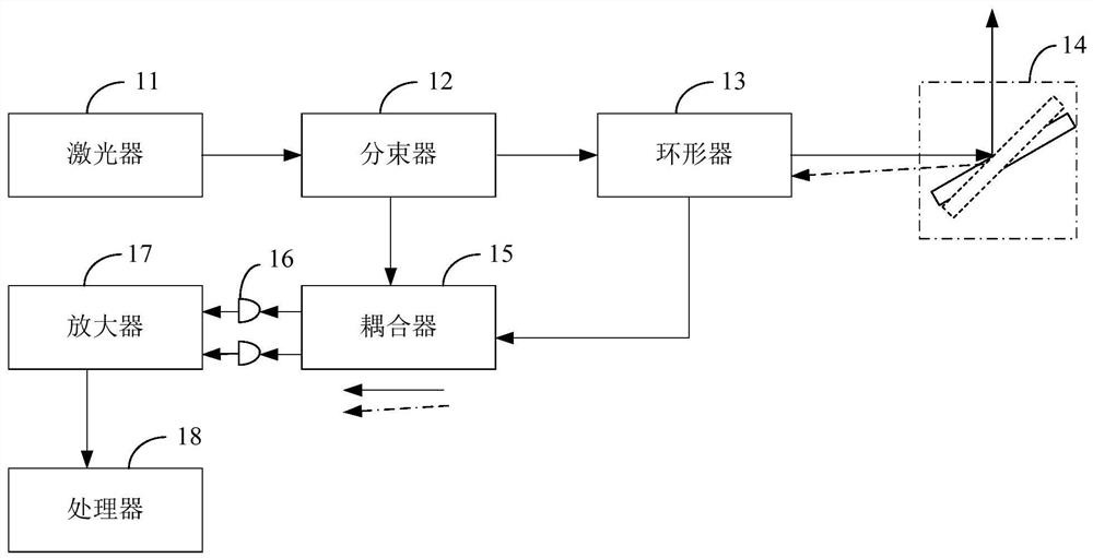
[0042] Figure 1 It is the structural diagram of the current coherent lidar. as Figure 1 As shown, the current coherent lidar includes a laser 11, a beam splitter 12, a circulator 13, a scanning mechanism 14, a coupler 15, a balanced photodiode 16, an amplifier 17 and a processor 18. After passing through the beam splitter 12, the laser emitted by the laser 11 is divided into local oscillator light and measurement light. The measuring light is emitted through the circulator 13 and spatial scanning is performed by the scanning mechanism 14. After the target scattering echo p...


PUM


Abstract

The invention discloses a coherent laser radar which comprises a laser, a local oscillation light path, a measuring light path, an echo light path, a scanning mechanism and a detection module. Laser emitted by the laser forms measuring light after passing through the measuring light path; the measuring light is emitted to a target object after passing through the scanning mechanism, and an echo of the target object reaches the detection module along an echo light path after passing through the scanning mechanism; laser emitted by the laser passes through the local oscillation light path to form local oscillation light, and the local oscillation light reaches the detection module; the local oscillation light path or the echo light path comprises a compensation driving mechanism, and the compensation driving mechanism is used for driving a target optical device in the local oscillation light path or the echo light path to change the direction of local oscillation light or echo; the detection module is used for detecting interference signals of echoes and local oscillation light. In the coherent laser radar, due to the action of the compensation driving mechanism, the local oscillation light is parallel to the echo, the effective interference signal is improved, and the performance of the coherent laser radar is further improved.

Description

technical field [0001] The embodiment of the invention relates to the optical field, in particular to a coherent lidar. Background technology [0002] Frequency modulated continuous wave (FMCW) system is an important radar type. Compared with traditional radar systems such as pulse radar and phase radar, it has the advantages of high precision, anti-jamming, no range blind area, direct speed measurement and simple structure, so it has good application prospects in many fields. Because it is based on the principle of laser interferometry, the echo scattered by the emitted measurement light hitting the target and the local oscillator light need to interfere to detect the effective signal. For the interference system using free space optical elements, the direction of echo is required to be strictly parallel to the direction of local oscillator in order to obtain a better interference signal. [0003] At present, for imaging coherent lidar, optical scanning mechanism, such as galvo ...

Claims


Application Information

Patent Timeline
Patent Type & Authority Applications(China)
IPC IPC(8): G01S17/02G01S7/4911G01S7/4912G01S7/481
CPCG01S17/02G01S7/4911G01S7/4912G01S7/4817G01S7/481
Inventor 不公告发明人
Owner SUZHOU LEIZHI SENSOR TECH CO LTD
Why Eureka
Try Eureka