
Distribution network cable corridor inspection device with buffer protection effect

A protection effect and cable technology, applied in the field of electric power, can solve problems such as humidity, poor feed stability, complex terrain, etc., and achieve the effects of remote inspection, avoiding blockage, and strong protection

Pending Publication Date: 2022-05-06
XI AN JIAOTONG UNIV
View PDF0 Cites 1 Cited by
  • Summary
  • Abstract
  • Description
  • Claims
  • Application Information

AI Technical Summary

Problems solved by technology

Cable tunnel: It is constructed in the form of a shallow trench, with an openable cover plate, but its internal space cannot meet the normal passage requirements of personnel, and is used to accommodate power cables and communication cables.
[0004] The existing distribution network cable corridors are generally underground concealed projects, with long distances, complex terrain, humidity, and the presence of toxic gases and combustible objects. Therefore, there is a certain degree of danger, and machines are generally used for inspections
It is very important for the safety inspection of urban pipe gallery. When the distribution network cable corridor is used, maintenance inspection is required. The traditional distribution network cable corridor inspection device has a simple structure and an effective shooting range; and the detection probe is exposed to the outside, and the overall protection is poor. ; The forward stability of the machine inspection is poor

Method used


Image

  • Distribution network cable corridor inspection device with buffer protection effect
  • Distribution network cable corridor inspection device with buffer protection effect
  • Distribution network cable corridor inspection device with buffer protection effect

Examples


Embodiment 1

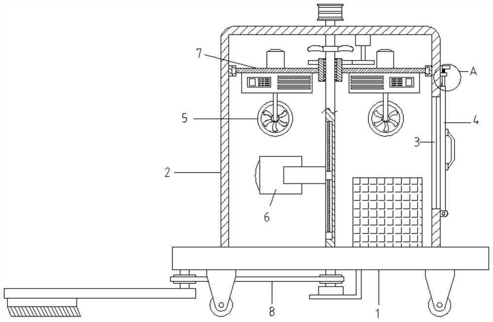
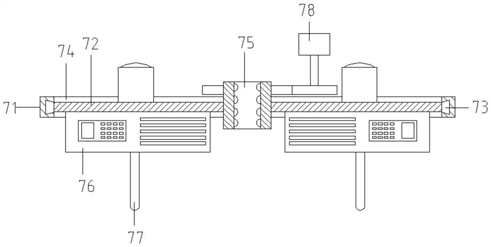
[0036]The invention provides a technical solution: a distribution network cable corridor inspection device with a buffer protection effect, including a car body 1, an elastic protective pad is arranged on the outside of the car body 1, and a limiting groove 10 is symmetrically opened on the upper end of the car body 1 (limiting slot 10 is set to dovetail shape), the bottom of car body 1 is provided with cleaning mechanism 8, and the upper end of car body 1 is fixed with rectangular cover 2, offers opening 3 on the side wall of rectangular cover 2, the outside of rectangular cover 2 A door sealing mechanism 4 is provided near the opening 3, a camera mechanism 6 is provided on the inner side of the rectangular cover 2, an environmental detection mechanism 7 is provided on the inner upper part of the rectangular cover 2, and several ventilation pipes are staggeredly plugged and fixed on the front and rear side walls of the rectangular cover 2. 5. The outer end of the ventilation p...

Embodiment 2

[0038] Based on the distribution network cable corridor inspection device with buffer protection effect provided by the first embodiment of the present application, the second embodiment of the present application proposes another distribution network cable corridor inspection device with buffer protection effect. Embodiment 2 is only a further form of Embodiment 1, and the implementation of Embodiment 2 will not affect the implementation of Embodiment 1 alone.

[0039] Embodiment 2 of the present invention will be further described below in conjunction with the accompanying drawings and implementation methods.

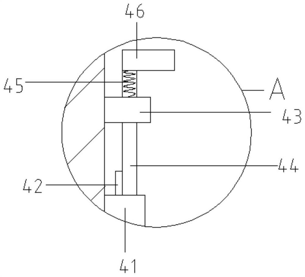
[0040] Compared with Embodiment 1, a specific door sealing mechanism 4 is provided in this embodiment including a sealing plate 41, a short block 42, a fixed block 43, a moving plate 44, a spring 45 and a handle 46, and the sealing plate 41 is installed through a rotating seat On the side wall of the rectangular cover 2, a blocking block is fixed on the inside of the ...

Embodiment 3

[0042] Based on the distribution network cable corridor inspection device with a buffer protection effect provided by the first embodiment of the present application, the third embodiment of the present application proposes another distribution network cable corridor inspection device with a buffer protection effect. Embodiment 3 is only a further form of Embodiment 1, and the implementation of Embodiment 3 will not affect the implementation of Embodiment 1 alone.

[0043] Embodiment 3 of the present invention will be further described below in conjunction with the accompanying drawings and implementation methods.

[0044] Compared with Embodiment 1, this embodiment provides a specific camera mechanism 6 , cleaning mechanism 8 and cleaning mechanism 9 .

[0045] Camera mechanism 6 comprises central shaft 61, screw mandrel 62, threaded block 63, U-shaped mounting block 64, camera 65, mounting groove 66, transmission roller 67, transmission motor 68 and L-shaped support plate 69...


PUM


Abstract

The invention discloses a distribution network cable corridor inspection device with a buffer protection effect in the technical field of electric power, which comprises a vehicle body, a sweeping mechanism is arranged at the bottom of the vehicle body, a rectangular cover is fixed at the upper end of the vehicle body, an opening is formed in the side wall of the rectangular cover, and a door sealing mechanism is arranged on the outer side of the rectangular cover near the opening. A camera shooting mechanism is arranged on the inner side of the rectangular cover, an environment detection mechanism is arranged on the upper portion of the inner side of the rectangular cover, a plurality of ventilation pipes are fixedly inserted into the front side wall and the rear side wall of the rectangular cover in a staggered mode, dustproof nets are arranged at the outer ends of the ventilation pipes, an exhaust fan is installed in the ventilation pipe on the rear side, and a cleaning mechanism is arranged on the outer side of the rectangular cover. Ventilation and heat dissipation can be conducted on the interior of the rectangular cover, air can be detected through a probe at the bottom of a detection instrument, the probe and the detection instrument are located in the rectangular cover, the protection performance is high, a dustproof net at the outer end of a ventilation pipe can be cleaned, and blockage is avoided.

Description

technical field [0001] The invention relates to the field of electric power technology, in particular to a distribution network cable corridor inspection device with a buffer protection effect. Background technique [0002] The underground comprehensive pipe gallery system not only solves the problem of urban traffic congestion, but also greatly facilitates the maintenance and repair of municipal facilities such as electricity, communications, gas, water supply and drainage. In addition, the system also has a certain effect of earthquake prevention and disaster reduction. Therefore, the underground comprehensive pipe gallery plays an important role in meeting the basic needs of people's livelihood and improving the comprehensive carrying capacity of the city. The comprehensive pipe gallery is the comprehensive corridor of underground urban pipelines, that is, to build a tunnel space underground in the city, integrating various engineering pipelines such as power, communicati...

Claims


Application Information

Patent Timeline
IPC IPC(8): H02G1/08H02G9/06
CPCH02G1/08H02G9/06
Inventor 曹晖孔德政康琼文王栩韬李牧遥
Owner XI AN JIAOTONG UNIV
Learn More