Pulpifying steam flow crushing and drying machine

A pulverizing dryer and steam flow technology, applied in dryers, drying gas arrangement, drying and other directions, can solve the problems of difficulty in achieving large-scale mills, limited impact speed and strength, and heat not used for drying, etc. Achieve the effect of saving drying process, improving crushing efficiency and high impact force

Pending Publication Date: 2022-05-10
林焕
View PDF1 Cites 0 Cited by
  • Summary
  • Abstract
  • Description
  • Claims
  • Application Information

AI Technical Summary

Problems solved by technology

The material is wet before crushing, it will stick together and cannot be attracted by the airflow to impact the target disk, so the material must be dried before impact crushing, and then crushed; although it is dry after the crushing is completed, the effect of steam is only Potential energy is provided, heat is not used for drying
Therefore, the pulverization and drying of materials in steam flow mill requires high energy consumption and high cost.
[0005] Second, the pulverized material of the steam flow mill is static before entering the supersonic nozzle, and needs to be sucked by the back pressure of the supersonic nozzle and then accelerated by the steam flow. lowering the velocity of the vapor stream
[0006] Third, the no

Method used


Image

  • Pulpifying steam flow crushing and drying machine
  • Pulpifying steam flow crushing and drying machine
  • Pulpifying steam flow crushing and drying machine

Examples


Embodiment Construction

[0048] The present invention will be described in detail below in conjunction with specific embodiments and accompanying drawings.

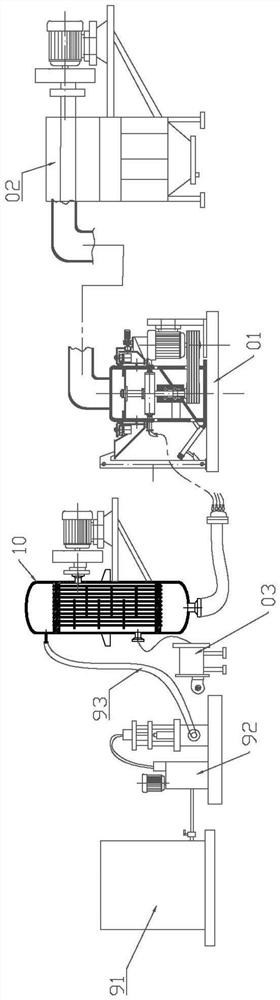
[0049] The pulping steam flow pulverizing dryer of the present embodiment, as Figure 1 to Figure 6As shown, it includes a slurry storage tank 91, a heater 10, an air mill 01 and a drying collector 02 connected in sequence from left to right. The slurry storage tank 91 is used to store wet mud materials, and the slurry storage tank 91 is connected with a slurry feeding Pump 92 and slurry inlet pipe 93, slurry inlet pump 92 is preferably a plunger pump, and slurry inlet pump 92 is connected to the inlet of the slurry storage cylinder 91 and the heater 10 through the slurry inlet tube 93, so as to transport the slurry material in the slurry storage cylinder 91 Entering the heater 10 for heating, the solid content of the slurry can be from 5% to 85%, and the preferred solid content is 50% to 70%.

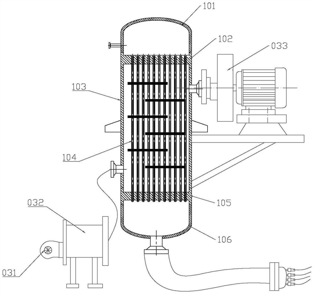
[0050] The heater 10 includes an upper tube box 10...


PUM


Abstract

The invention relates to the technical field of material crushing and drying, in particular to a slurrying steam flow crushing and drying machine which comprises a slurry storage cylinder, a heater, an air mill and a drying and collecting machine which are sequentially communicated, the slurry storage cylinder is connected with a slurry inlet pump and a slurry inlet pipe, and the slurry inlet pump is connected with the slurry storage cylinder and the heater through the slurry inlet pipe; materials in the slurry storage cylinder are conveyed into the heater to be heated; the air mill comprises a machine shell, a main shaft, a rotating target, a plurality of Laval nozzles, a classifying screen and a first driving mechanism used for driving the main shaft to rotate, the main shaft is rotatably and longitudinally arranged in the machine shell, the main shaft penetrates through and fixes the rotating target and the classifying screen, the classifying screen is located above the rotating target, and the Laval nozzles are arranged around the circumferential side of the rotating target. Each Laval nozzle is communicated with an outlet of the heater through a steam slurry pipe; a discharging port is formed in the position, located above the classifying screen, of the machine shell and connected with a drying and collecting machine through a discharging pipe, and the drying and collecting machine is provided with an exhaust mechanism for conducting air draft on the discharging pipe. And the cost is low, and the crushing efficiency is high.

Description

technical field [0001] The invention relates to the technical field of crushing and drying of materials, in particular to a slurrying steam flow crushing and drying machine. Background technique [0002] Jet milling uses the energy of compressed air or superheated steam to make materials collide with each other, collide and rub to achieve ultra-fine pulverization. Its products are widely used in industries such as chemical industry, ceramics, coatings, electronic materials and medicine. The jet milling equipment currently on the market There are mainly fluidized bed jet mills, which arrange several nozzles two-dimensionally or three-dimensionally in the main shell of the mill. The airflow accelerates through the nozzles and carries the materials to meet at one point. The materials collide with each other at high speed and rub against each other to achieve crushing. Expansion drives the materials into suspension in the fluidized bed, and crushing is the collision and friction...

Claims


Application Information

Patent Timeline
IPC IPC(8): B02C21/00B02C19/06B02C23/10F26B21/00
CPCB02C21/00B02C19/066B02C23/10F26B21/005
Inventor 林焕
Owner 林焕
Why Eureka
Try Eureka