
Thermal protection design method for leading edge of hypersonic aircraft based on three-dimensional orthogonal woven composite material

A composite material and hypersonic technology, applied in computer-aided design, design optimization/simulation, instruments, etc., can solve the problems of consuming extra energy of hypersonic aircraft, reducing the temperature of leading edge components, reducing the temperature of leading edge, etc., to achieve lower temperature , reduce the temperature of the leading edge, and realize the design effect

Pending Publication Date: 2022-05-10
NANJING UNIV OF AERONAUTICS & ASTRONAUTICS
View PDF0 Cites 1 Cited by
  • Summary
  • Abstract
  • Description
  • Claims
  • Application Information

AI Technical Summary

Problems solved by technology

[0008] The present invention is aimed at the thermal protection requirements of hypersonic leading edge components. Considering that the introduction of coolant in the current thermal protection design will consume the extra energy of the hypersonic aircraft, the present invention proposes a hypersonic composite material based on three-dimensional orthogonally woven composite materials. Design method for aircraft leading edge thermal protection. This method reduces the temperature of the leading edge components through the optimization of the macroscopic temperature field of the three-dimensional orthogonally woven ceramic matrix composite leading edge components and the collaborative design of the mesoscopic woven structure. Effective reduction of leading edge temperature without cooling measures

Method used


Image

  • Thermal protection design method for leading edge of hypersonic aircraft based on three-dimensional orthogonal woven composite material
  • Thermal protection design method for leading edge of hypersonic aircraft based on three-dimensional orthogonal woven composite material
  • Thermal protection design method for leading edge of hypersonic aircraft based on three-dimensional orthogonal woven composite material

Examples


Embodiment 1

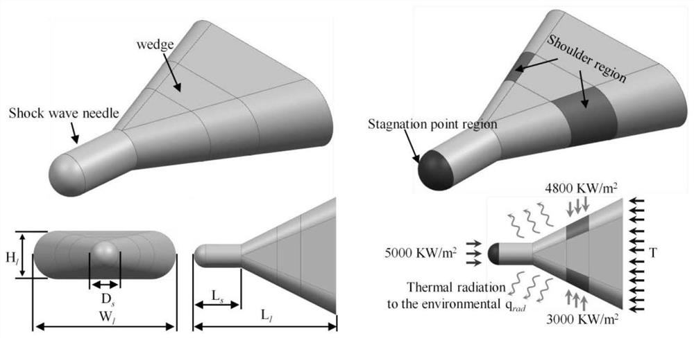
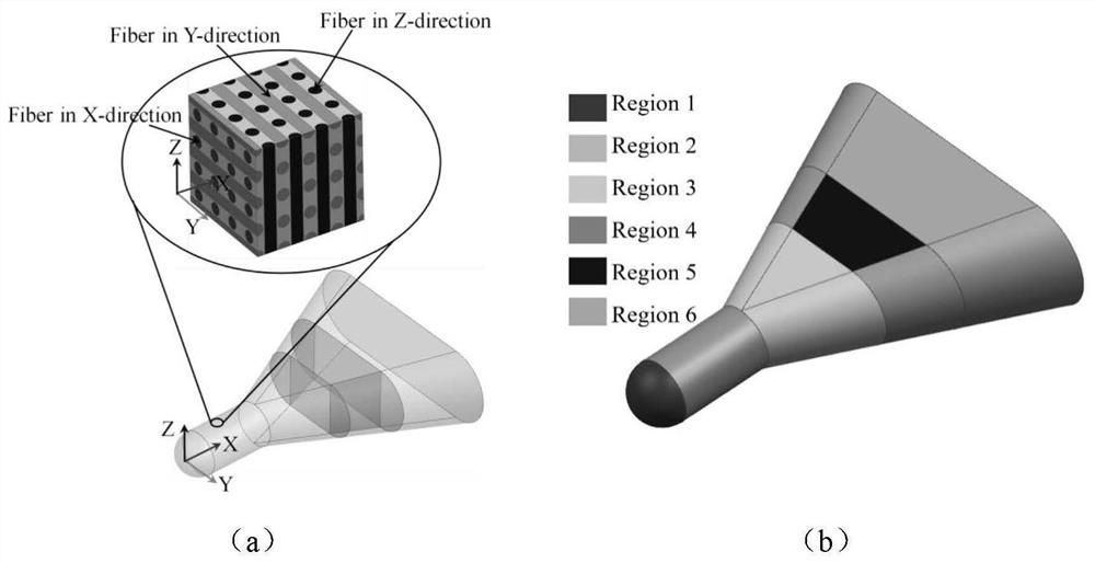
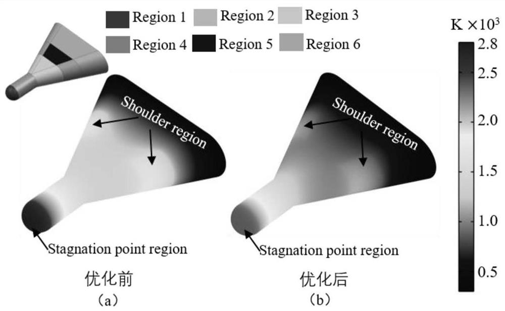
[0072] Taking the leading edge of a hypersonic vehicle as an example, the thermal protection design method for the leading edge of a hypersonic vehicle based on three-dimensional orthogonally woven composite materials is described. figure 1 As shown, the geometric characteristics of the leading edge structure and the calculation boundary conditions; the leading edge is mainly composed of two parts: the shock wave needle and the shoulder; the stagnation point area of ​​the shock wave needle is hemispherical, the diameter Ds = 50mm, the length of the shock wave needle Ls = 75mm, the length of the leading edge Ll=300mm, the leading edge width Wl=250mm, the leading edge height Hl=85mm, the stagnation area has the strongest aerodynamic heating, the heat flux is 5000KW / m2, and the heat flux of the shoulder area is 3000KW / m 2 , the bottom of the leading edge is set as a constant temperature boundary, T=293.15K, and the heat flux of other surfaces is 500W / m 2 , at the same time, con...


PUM


Abstract

The invention discloses a hypersonic aircraft leading edge thermal protection design method based on a three-dimensional orthogonal woven composite material, belongs to the technical field of engineering thermophysics, and can effectively reduce the leading edge temperature under the condition of not increasing cooling measures. The method comprises the following steps: firstly, establishing a multivariable linear regression model, and searching theoretical optimization heat conduction configuration of a leading edge, so that the temperature of a leading edge component is effectively reduced; secondly, establishing a general calculation formula suitable for calculating anisotropic heat conductivity coefficients of different woven structures of the three-dimensional orthogonal woven ceramic matrix composite, wherein the general calculation formula is used for guiding a mesoscopic woven structure of the three-dimensional orthogonal woven ceramic matrix composite; finally, an optimization result obtained by the multivariable linear regression model is directly combined with a general formula, mesoscopic woven structures needed by different areas are designed, and collaborative design of leading edge macroscopic temperature optimization and the three-dimensional orthogonal woven ceramic matrix composite mesoscopic woven structure is achieved.

Description

technical field [0001] The invention belongs to the technical field of engineering thermophysics, and in particular relates to a design method for thermal protection of the leading edge of a hypersonic aircraft based on a three-dimensional orthogonally woven composite material. Background technique [0002] As the hypersonic vehicle flies at a high Mach number, kinetic energy is converted into internal energy at the stagnation point of the leading edge, causing a sharp increase in the temperature of the head region (Bull JD, Rasky DJ, Tran HK, et al.Material Response of DiborideMatrix Composites to Low Pressure Simulated Hypersonic Flows. NASA CP-32351994; Part 2(5):653-673.). Due to the severe aerodynamic heating of hypersonic vehicles, the material of the leading edge of the vehicle must meet the thermal protection requirements. Compared with traditional materials, ceramic matrix composites (CMCs) have excellent temperature resistance and high-temperature mechanical prope...

Claims


Application Information

Patent Timeline
IPC IPC(8): G06F30/15G06F30/23G06F113/26G06F119/08
CPCG06F30/15G06F30/23G06F2113/26G06F2119/08
Inventor 赵陈伟毛军逵屠泽灿陈雄斌简辉
Owner NANJING UNIV OF AERONAUTICS & ASTRONAUTICS
Learn More