Error compensation type laser welding equipment with crack detection function

An error compensation and laser welding technology, applied in the field of error compensation laser welding equipment, can solve the problems of staff health protection, failure to consider welding exhaust gas purification, failure to consider welding exhaust gas recovery and reuse, etc., to achieve adjustment of welding position, The effect of flexible welding positions

Inactive Publication Date: 2022-05-13
江苏洛柳精密科技有限公司
View PDF13 Cites 4 Cited by
  • Summary
  • Abstract
  • Description
  • Claims
  • Application Information

AI Technical Summary

Problems solved by technology

The laser welding equipment and laser welding method of the present invention realize the automatic flow welding of workpieces, can adapt to the welding needs of multiple angles of workpieces, effectively improve the welding efficiency of workpieces and reduce costs.” When the welding equipment is used, it fails to consider welding The recovery and reuse of exhaust gas, and the purification of welding exhaust gas has not been considered, and the health of the staff has not been guaranteed.

Method used


Image

  • Error compensation type laser welding equipment with crack detection function
  • Error compensation type laser welding equipment with crack detection function
  • Error compensation type laser welding equipment with crack detection function

Examples


Embodiment 1

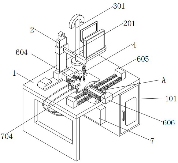
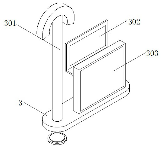
[0044] see figure 1 , image 3 and Figure 4 , an embodiment provided by the present invention: an error-compensated laser welding device with crack detection, including an operation table body 1 and a welding torch body 4, a stand 2 is installed on the top of the operation table body 1, and the stand 2 The surface of the telescopic cross bar 201 is installed, and the tail end bottom of the telescopic cross bar 201 is equipped with a welding torch body 4;

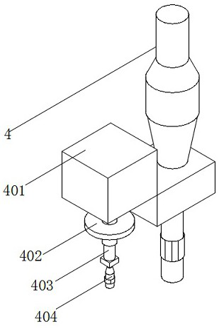
[0045] The surface of the welding gun body 4 is sleeved with an L-shaped connection block 401, and the bottom of the connection block 401 is equipped with an electric telescopic rod 403, and the electric telescopic rod 403 is located on one side of the welding torch body 4, and the surface of the electric telescopic rod 403 is socketed There is a set plate 402, a symmetrically arranged crack detector 405 is installed on the bottom of the set plate 402, a welding head 404 is installed on the bottom of the electric telescop...

Embodiment 2

[0049] see figure 1 and Figure 6 , an embodiment provided by the present invention: an error-compensated laser welding device with crack detection, including a No. 1 chute 6, and a No. 1 chute 6 is installed on the top of the operating table A No. 1 slider 601 is fitted inside, and No. 2 chute 602 is connected to the top of No. 1 slider 601, and No. 2 chute 602 is vertically arranged with No. 1 chute 6. The interior of No. 2 chute 602 is slidably installed with No. 2 slider 603, the top of No. 2 slider 603 is equipped with a rectangular welded bottom plate 604, No. 1 slider 601 and No. 2 slider 603 are magnet blocks, and No. 1 magnet is installed at both ends of No. 1 chute 6. Iron 605, the two ends of No. 2 chute 602 are equipped with No. 2 electromagnet 606.

[0050] Specifically, after one group of No. 1 electromagnets 605 is energized, No. 1 slider 601 can be driven by the electromagnetic adsorption of No. 1 electromagnet 605 to drive No. 2 chute 602 and welding bottom ...

Embodiment 3

[0053] see figure 1 and Figure 5 , an embodiment provided by the present invention: an error-compensated laser welding device with crack detection, including an adjustable support box 5, the bottom of both ends of the second chute 602 is equipped with an adjustable support box 5, the adjustable support box The top wall of 5 is equipped with electric push rods 501 equidistantly arranged, and a pressure detector 502 is installed at the bottom end of the electric push rods 501. The sensor 504 and the roller frame 503 are installed on the bottom of the pressure detector 502, and the two sets of pressure sensors are electrically connected.

[0054] Specifically, when the welding bottom plate 604 moves along the No. 2 chute 602, the gravity of the welding bottom plate 604 and the objects to be welded placed on the top will cause the center of gravity to be off when the welding bottom plate 604 moves to the two ends of the No. 2 chute 602. Move, and then make the welding bottom pl...


PUM


Abstract

The error compensation type laser welding equipment with the crack detection function comprises an operation table body, a vertical frame is installed at the top of the operation table body, and a welding gun body is installed at the bottom of the tail end of a telescopic transverse rod; the surface of the welding gun body is sleeved with a connecting block, an electric telescopic rod is installed at the bottom of the connecting block, the surface of the electric telescopic rod is sleeved with a sleeve disc, a crack detector is installed at the bottom of the sleeve disc, a welding head is installed at the bottom of the electric telescopic rod, and the electric telescopic rod is electrically connected with the crack detector. A first sliding groove is formed in the top of the operation table body, a storage cabinet is installed on one side of the bottom of the operation table body, and a tail gas purification box is installed on the surface of one side of the storage cabinet. By arranging the welding gun body, the welding head, the electric telescopic rod and the crack detector, crack compensation welding treatment can be conducted while the welding equipment is assisted to achieve link crack detection, and the welding quality is guaranteed.

Description

technical field [0001] The invention relates to the technical field of laser welding, in particular to an error compensation type laser welding equipment with crack detection. Background technique [0002] Laser welding equipment is a machine for laser material processing. Compared with traditional welding equipment, laser welding has the advantages of being able to weld at room temperature or under special conditions and the welding equipment is simple. In addition, laser welding can also perform micro welding, welding For parts that are difficult to access, non-contact long-distance welding has great flexibility. Therefore, with the diversity of angle changes between parts of industrial processing machines, laser welding has gradually become the first choice for welding equipment. [0003] The defects of existing laser welding equipment are: [0004] 1. Patent document CN107570868A discloses a laser welding position error compensation method and laser welding equipment, "...

Claims


Application Information

Patent Timeline
Patent Type & Authority Applications(China)
IPC IPC(8): B23K26/21B23K26/70
CPCB23K26/21B23K26/702
Inventor 黄稳岩黄志军
Owner 江苏洛柳精密科技有限公司
Why Eureka
Try Eureka