Hip joint bone cement interval blister mould

A bone cement and hip joint technology, applied in the field of medical devices, can solve the problems of poor applicability and inability to fine-tune the cement interval, and achieve the effect of small amplitude, short sliding distance and small resistance value

Inactive Publication Date: 2022-05-13
源利腾达(西安)科技有限公司 +1
View PDF21 Cites 2 Cited by
  • Summary
  • Abstract
  • Description
  • Claims
  • Application Information

AI Technical Summary

Problems solved by technology

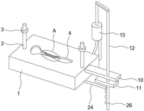
[0003] Existing cement spacers are generally formed by moulds. Application No. 202021117338.2 discloses a blister mold for bone cement spacers of the hip joint, which includes a blister body and a metal handle. The taper is consistent with the conventional hip femoral prosthesis, with a taper of 12 / 14; the neck thickness and neck-shaft angle of the metal handle are consistent with the conventional hip femoral prosthesis; Arc-shaped, tapering, flatter and thinner than conventional hip femoral prosthesis body; blister body includes hip femoral bone cement spacer blister model that matches the shape of conventional hip femoral prosthesis cavity; the hip joint femoral bone cement spacer and the femoral metal handle generated by the first blister model cavity are placed in it to form a hip joint bone cement spacer; but there are the following problems: the molded cement spacer cannot conform to the radian of the patient's hip joint The situation is fine-tuned, and the applicability is poor

Method used


Image

  • Hip joint bone cement interval blister mould
  • Hip joint bone cement interval blister mould
  • Hip joint bone cement interval blister mould

Examples


Embodiment Construction

[0026] The following will clearly and completely describe the technical solutions in the embodiments of the present invention with reference to the accompanying drawings in the embodiments of the present invention. Obviously, the described embodiments are only some, not all, embodiments of the present invention.

[0027] In describing the present invention, it should be understood that the terms "upper", "lower", "front", "rear", "left", "right", "top", "bottom", "inner", " The orientation or positional relationship indicated by "outside", etc. is based on the orientation or positional relationship shown in the drawings, and is only for the convenience of describing the present invention and simplifying the description, rather than indicating or implying that the referred device or element must have a specific orientation, so as to Specific orientation configurations and operations, therefore, are not to be construed as limitations on the invention.

[0028] refer to Figure ...


PUM


Abstract

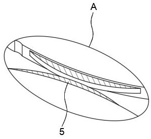
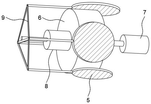
The invention relates to the technical field of cement interval forming, and discloses a hip joint bone cement interval blister blister mold which comprises a lower mold body, a cavity is formed in the lower mold body, a sliding opening is formed in the inner wall of the cavity, a radian adjusting mechanism is arranged in the lower mold body, and the radian adjusting mechanism comprises a cavity formed in the lower mold body. The cavity is communicated with the sliding opening, a motor is fixed in the cavity, a cylinder is fixed to the driving end of the motor, a telescopic rod is fixed to the end, away from the motor, of the cylinder, a frame is fixed to the driving end of the telescopic rod, and a plurality of connecting rods are fixed to the outer wall of the frame. The circular plate is replaced according to the requirement for the radian of the hip joint, the radian of the formed cement interval is changed, the applicability is higher, meanwhile, after the circular plate is replaced, self-adaptive change of the moving distance of the sealing plate is automatically conducted, the sealing performance between the sliding opening and the circular plate is guaranteed, and the sealing effect is better. Swing of the swing rods accelerates demolding of the cement intervals.

Description

technical field [0001] The invention relates to the technical field of medical devices, in particular to a hip joint bone cement spacer blister mold. Background technique [0002] Infection after artificial hip arthroplasty is a complication of artificial hip arthroplasty, which will cause great mental pain to patients, great financial losses, and great pressure on doctors. At present, the treatment method for infection after artificial hip replacement is as follows: firstly, the original hip prosthesis is taken out for thorough debridement, and granular antibiotic-containing bone cement is used to fill the bone marrow cavity as a temporary hip joint barrier and then sterilized. After the infection is controlled, the filled granular bone cement is removed, and a new artificial hip joint is placed again. [0003] Existing cement spacers are generally formed by moulds. Application No. 202021117338.2 discloses a blister mold for bone cement spacers of the hip joint, which incl...

Claims


Application Information

Patent Timeline
Patent Type & Authority Applications(China)
IPC IPC(8): B29C51/30B29C51/36B29C51/44B29C37/00
CPCB29C51/303B29C51/36B29C51/44B29C37/0003B29L2031/7532
Inventor 陈胜伟左丽丽
Owner 源利腾达(西安)科技有限公司
Why Eureka
Try Eureka