Eureka AIR delivers breakthrough ideas for toughest innovation challenges, trusted by R&D personnel around the world.

Diaphragm-free micro-electrolytic cell-photovoltaic hydrogen production system and method

A hydrogen production system and micro-electrolyzer technology, applied in the field of non-diaphragm micro-electrolyzer-photovoltaic hydrogen production system, can solve the problems of energy consumption, substandard temperature, affecting electrolysis efficiency, etc. The effect of photovoltaic power generation efficiency

Pending Publication Date: 2022-05-13
HUANENG CLEAN ENERGY RES INST
View PDF6 Cites 0 Cited by
  • Summary
  • Abstract
  • Description
  • Claims
  • Application Information

AI Technical Summary

Problems solved by technology

On the other hand, the output of the micro-electrolyzer is increased after being enlarged, but the electrolysis needs to be carried out at a certain temperature. If the temperature is not up to standard, it will directly affect the electrolysis efficiency.
Furthermore, in traditional photovoltaic power generation, in order to improve the efficiency of photovoltaic power generation, it is necessary to control the temperature of the photovoltaic panel, and reducing the temperature of the photovoltaic panel will also cause a certain amount of energy consumption

Method used


Image

  • Diaphragm-free micro-electrolytic cell-photovoltaic hydrogen production system and method
  • Diaphragm-free micro-electrolytic cell-photovoltaic hydrogen production system and method
  • Diaphragm-free micro-electrolytic cell-photovoltaic hydrogen production system and method

Examples


Embodiment Construction

[0046] Embodiments of the invention are described in detail below, examples of which are illustrated in the accompanying drawings. The embodiments described below by referring to the figures are exemplary and are intended to explain the present invention and should not be construed as limiting the present invention.

[0047] The current controllers, temperature sensors, inverters, circulation pumps, etc. used in the diaphragmless micro-electrolyzer-photovoltaic hydrogen production system of the embodiment of the present invention can all be obtained through commercial channels.

[0048] The diaphragmless micro-electrolyzer-photovoltaic hydrogen production system of the embodiment of the present invention will be described below in conjunction with the accompanying drawings.

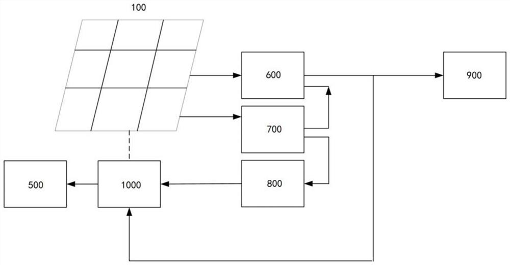
[0049] figure 1 It is a simple structural diagram of a micro-electrolyzer without a diaphragm-photovoltaic hydrogen production system according to an embodiment of the present invention.

[0050] Such a...


PUM

PropertyMeasurementUnit
lengthaaaaaaaaaa
depthaaaaaaaaaa
lengthaaaaaaaaaa

Abstract

The invention discloses a diaphragm-free micro-electrolytic cell-photovoltaic hydrogen production system and method. The diaphragm-free micro-electrolytic cell-photovoltaic hydrogen production system comprises a photovoltaic panel, a diaphragm-free micro-electrolytic cell amplifying device, a micro-electrolytic cell conveying system and a hydrogen storage system, the diaphragm-free micro-electrolytic cell amplifying device is mounted on the surface of one side, back to the sunlight, of the photovoltaic panel in a fitting manner; the diaphragm-free micro-electrolytic cell amplifying device comprises a plurality of micro-electrolytic cell arrays; a current controller and a temperature sensor are installed on the side, right facing the sunlight, of the photovoltaic panel. The current controller is connected with the inverter and the diaphragm-free micro-electrolysis amplifying device; the temperature sensor is connected with the current controller and the micro-electrolysis cell conveying system; and the micro-electrolysis cell conveying system comprises a power device which is communicated with the diaphragm-free micro-electrolysis cell amplifying device. According to the diaphragm-free micro-electrolytic cell-photovoltaic hydrogen production system, the temperature of the photovoltaic panel can be reduced, the photovoltaic power generation efficiency can be improved, meanwhile, the temperature in the diaphragm-free micro-electrolytic cell amplification device can be improved, and the electrolytic efficiency can be improved.

Description

technical field [0001] The invention belongs to the field of electrolytic hydrogen production, and in particular relates to a diaphragm-free micro-electrolyzer-photovoltaic hydrogen production system and method, in which electric energy generated by photovoltaics is electrolyzed to produce hydrogen through a diaphragm-free micro-electrolyzer. Background technique [0002] At present, photovoltaic power generation has become the most economical clean energy in the world, and its cost per unit of electricity continues to decline. The low cost of electricity per unit of photovoltaic power generation brings opportunities to reduce costs for hydrogen production from electrolyzed water. Then, using sufficient and economical photovoltaic power to split water to produce green hydrogen can continuously expand the application scale of green hydrogen and accelerate the realization of the goals of carbon reduction and decarbonization in countries around the world. The existing mainstrea...

Claims


Application Information

Patent Timeline
Patent Type & Authority Applications(China)
IPC IPC(8): C25B9/65C25B9/67C25B9/70C25B15/08C25B15/02H02J3/38H02S40/32
CPCC25B9/65C25B9/67C25B9/70C25B15/08C25B15/02H02S40/32H02J3/381H02J2300/24Y02E10/50Y02E60/36
Inventor 王韬王鹏杰刘丽萍王凡郭海礁王金意
Owner HUANENG CLEAN ENERGY RES INST
Why Eureka
Eureka Blog
Learn More