
Recyclable three-dimensional textile printing and dyeing equipment

A kind of printing and dyeing equipment, three-dimensional technology, applied in the field of three-dimensional textile printing and dyeing equipment, can solve the problems of affecting the quality of finished products, waste of dyestuffs, not considering the drying function of printing and dyeing equipment, etc., so as to improve the quality of finished products and increase the number of recycling times Effect

Pending Publication Date: 2022-05-13
海安富邦纺织科技有限公司
View PDF12 Cites 0 Cited by
  • Summary
  • Abstract
  • Description
  • Claims
  • Application Information

AI Technical Summary

Problems solved by technology

The fast printing and dyeing equipment without pre-shrinking dyeing, when fast printing and dyeing operation is required, the user puts the cloth into the printing and dyeing room from the inlet, and under the action of the first motor, the stirring rod rotates rapidly to stir and mix the solidified dye at the bottom of the printing and dyeing room , under the action of the water pump, the dye with high concentration at the bottom is sprayed from the nozzle on one side through the connecting pipe, and the complete printing and dyeing operation is carried out on the cloth. Pour out the excess water inside the printing and dyeing room, and then tilt to the right after the dye on the surface of the cloth is basically dripped, and the cloth slides out from the inside of the printing and dyeing room. Pour out the water inside, without considering that most of the existing printing and dyeing equipment do not have the function of recycling, which will easily cause waste of dyes;
[0005] 2. Patent document CN213120232U, which discloses a device for recovering waste heat from printing and dyeing equipment, including a printing and dyeing equipment body, the bottom of the printing and dyeing equipment body is connected to a first drain pipe, and one end of the first drain pipe is connected to a liquid filter , the other side of the liquid filter is connected with a waste water tank through a pipeline, the side of the waste water tank is connected with a second water inlet pipe, and one end of the second water inlet pipe is connected with a heat exchanger; the utility model, by setting the waste water tank, can Store the wastewater generated by printing and dyeing, and filter the wastewater through a liquid filter. By setting up a water storage tank and a heat exchanger, it is possible to exchange heat between the wastewater with temperature and cold water, thereby heating the clean cold water. Carry out heat energy recovery, by setting up the exhaust hood, exhaust pipe, air outlet hood and condenser, the waste gas with thermal energy can be recovered to achieve the purpose of saving energy, but the printing and dyeing equipment in the above-mentioned public documents mainly use thermal energy Recycling to save resources does not take into account that after printing and dyeing, the surface of the textile fabric is prone to wrinkles, etc., which will easily affect the quality of the finished product after drying;
The automatic conveying device used for printing and dyeing equipment has the advantages of simple operation and no need to consume too much manpower. However, the printing and dyeing equipment in the above-mentioned public documents mainly considers how to facilitate the transportation of the printed and dyed textile cloth, and does not take into account the current situation. Some printing and dyeing equipment do not have the problem of drying function, which is not conducive to improving production efficiency

Method used


Image

  • Recyclable three-dimensional textile printing and dyeing equipment
  • Recyclable three-dimensional textile printing and dyeing equipment
  • Recyclable three-dimensional textile printing and dyeing equipment

Examples


Embodiment Construction

[0040] The following will clearly and completely describe the technical solutions in the embodiments of the present invention with reference to the accompanying drawings in the embodiments of the present invention. Obviously, the described embodiments are only some, not all, embodiments of the present invention. Based on the embodiments of the present invention, all other embodiments obtained by persons of ordinary skill in the art without making creative efforts belong to the protection scope of the present invention.

[0041] In the description of the present invention, it should be noted that the terms "upper", "lower", "inner", "outer", "front end", "rear end", "both ends", "one end", "another end" The orientation or positional relationship indicated by etc. is based on the orientation or positional relationship shown in the drawings, and is only for the convenience of describing the present invention and simplifying the description, rather than indicating or implying that ...


PUM


Abstract

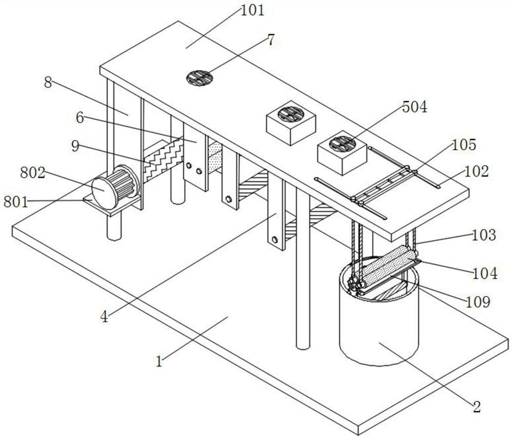
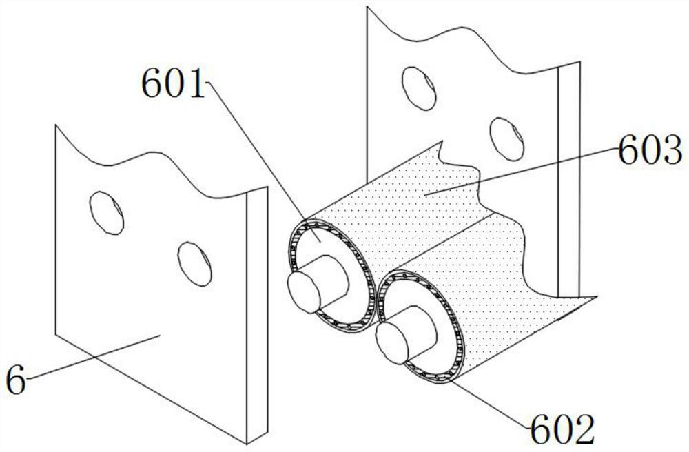
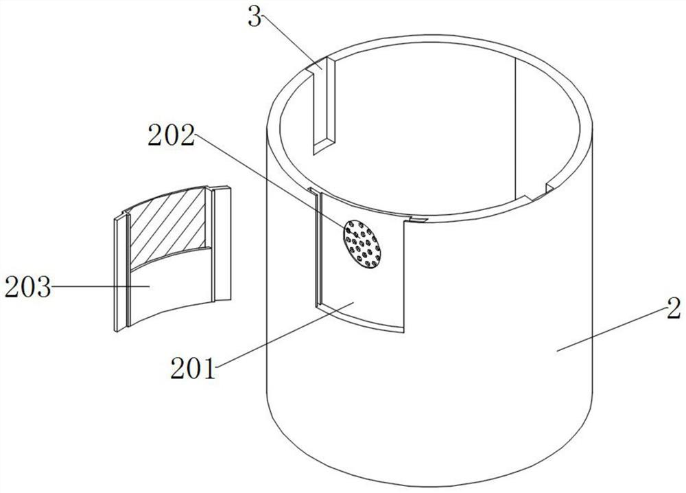
The recycling three-dimensional textile printing and dyeing equipment comprises a base and a first connecting plate, two sets of supporting columns arranged front and back are installed at the top of the base, and a top plate is installed at the tops of the supporting columns; symmetrically-arranged sliding grooves are formed in the top of the top plate in a penetrating mode, connecting rods which are symmetrically arranged front and back are slidably installed in the sliding grooves, connecting blocks are installed at the top ends of the front connecting rod and the rear connecting rod, and inserting holes which are distributed at equal intervals are formed in the back face of the front connecting block. Inserting rods which are arranged at equal intervals are installed on the front face of the rear connecting block, extrusion rollers are installed at the bottom ends of the front connecting rod and the rear connecting rod, and connecting holes are formed in the outer walls of one sides of the two extrusion rollers. By arranging the base, the sliding grooves, the extrusion rollers and the connecting blocks, the connecting blocks are moved, then the connecting rods are driven to move in the sliding grooves, redundant dye on textile cloth is extruded and scraped off through the extrusion rollers, and then the number of times of cyclic utilization of the dye is increased.

Description

technical field [0001] The invention relates to the technical field of textile production, in particular to a recycled three-dimensional textile printing and dyeing equipment. Background technique [0002] In the process of textile cloth production, it is usually necessary to print and dye the textile cloth to print and dye the cloth into different patterns and colors according to actual needs, but the existing textile printing and dyeing equipment cannot recycle the dye during use, which is extremely It is easy to waste dyestuffs, therefore, there is an urgent need for a recyclable three-dimensional textile printing and dyeing equipment. [0003] The defective that existing printing and dyeing equipment exists is: [0004] 1. The patent document CN210975144U discloses a fast printing and dyeing equipment without pre-shrinking dyeing, which includes a box body. Openings are fixedly installed on the left and right sides of the box body. board, and movable blocks are fixedly...

Claims


Application Information

Patent Timeline
Patent Type & Authority Applications(China)
IPC IPC(8): D06B3/10D06B15/00D06B15/02D06B17/04D06B23/20D06C15/02
CPCD06B3/10D06B15/02D06B23/20D06B15/00D06B17/04D06C15/02
Inventor 蒋高稳唐志钢
Owner 海安富邦纺织科技有限公司
Learn More