
Bidirectional variable gain amplifier based on active cross coupling structure

A gain amplifier and cross-coupling technology, used in bidirectional amplifiers, amplifiers, high-frequency amplifiers, etc., can solve problems such as poor additional phase shift indicators, and achieve the effect of high maximum gain, low additional phase shift, and reduced additional phase shift.

Pending Publication Date: 2022-05-13
UNIV OF ELECTRONICS SCI & TECH OF CHINA
View PDF2 Cites 2 Cited by
  • Summary
  • Abstract
  • Description
  • Claims
  • Application Information

AI Technical Summary

Problems solved by technology

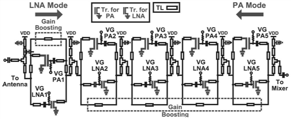
Such as the literature "J.Pang et al.,"A 28.16-Gb / s Area-Efficient 60-GHz CMOS Bidirectional Transceiver for IEEE 802.11ay,"in IEEE Transactions on Microwave Theory and Techniques,vol.68,no.1,pp.252 -263, Jan.2020, doi:10.1109 / TMTT.2019.2938160." discloses a bidirectional variable gain amplifier, such as figure 1 As shown, the variable gain amplifier used in the bidirectional transceiver only uses a single-ended common-source amplifier tube, and the gain adjustment function is realized by controlling the grid bias voltage of the amplifier tube; because the influence of the amplifier tube Cgd cannot be eliminated, its input and output impedance As the gain state changes, the insertion phase shift also changes in the emission, resulting in a very poor index for its additive phase shift

Method used


Image

  • Bidirectional variable gain amplifier based on active cross coupling structure
  • Bidirectional variable gain amplifier based on active cross coupling structure
  • Bidirectional variable gain amplifier based on active cross coupling structure

Examples


Embodiment Construction

[0025] The present invention will be described in further detail below in conjunction with the accompanying drawings and embodiments.

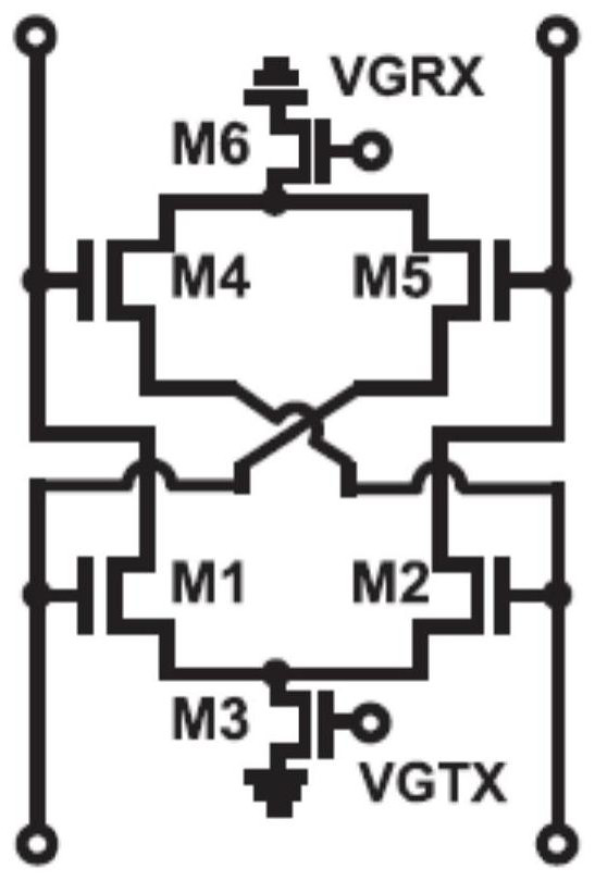
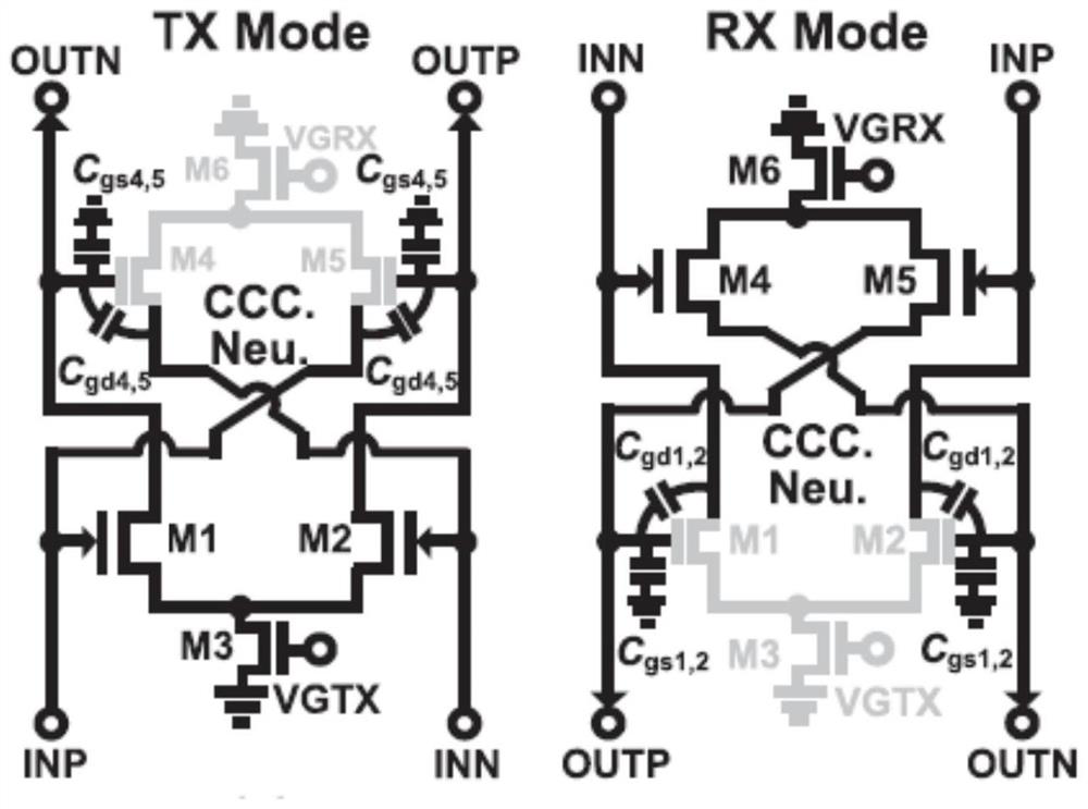
[0026] This embodiment provides a bidirectional variable gain amplifier based on an active cross-coupling structure, and its circuit structure is as follows Figure 4 As shown, through this structure, bidirectional gain adjustment is realized, and compared with the existing differential bidirectional variable gain amplifier, this embodiment has lower additional phase shift and higher maximum gain.

[0027] Specifically, the bidirectional variable gain amplification based on the active cross-coupling structure includes: eight common source transistors M 1 ~ M 8 , eight DC blocking capacitors C 1 ~C 8 , eight insulation resistors R; among them, the common source tube M 1 ~ M 8 The source stages are all grounded, and the common source tube M 1 with M 2 The gates of the gates are connected in parallel with the cross-blocking resistor R and ...


PUM


Abstract

The invention belongs to the technical field of wireless communication, and provides a bidirectional variable gain amplifier based on an active cross coupling structure, which is used for solving the problems of high additional phase shift, low maximum gain and the like of the existing differential bidirectional variable gain amplifier. The circuit is composed of two groups of active cross coupling circuits, and bidirectional control is realized through interconnection of input and output ports of the two groups of active cross coupling structures; the sum of drain electrode direct currents in different gain states is not changed, so that better insertion phase shift is realized; due to the fact that all stray capacitors Cgd in the amplifier are all counteracted, lower additional phase shift is achieved. As a tail current source is cancelled, the drain-source voltage difference is VDD, and a higher maximum gain state is realized. In conclusion, the bidirectional variable gain amplifier based on the active cross coupling structure provided by the invention has lower additional phase shift and larger maximum gain.

Description

technical field [0001] The invention belongs to the technical field of wireless communication, relates to a bidirectional variable gain amplifier in a transceiver of a communication system, and specifically provides a bidirectional variable gain amplifier based on an active cross-coupling differential common source structure. Background technique [0002] Most of the current transceiver structures are transmitter links and receiver links that work independently, occupying twice the single-link chip area; in recent years, research hotspots have focused on high-performance 5G millimeter-wave phased array transceivers; however, In order to realize the 5G millimeter wave DP-MIMO system that requires a large number of transceiver links, the traditional phased array solution requires a large total transceiver chip area and high chip cost; and due to the reduction of the array antenna spacing at millimeter wave frequencies Small, in order to reduce the low-loss distribution from th...

Claims


Application Information

Patent Timeline
Patent Type & Authority Applications(China)
IPC IPC(8): H03F3/62H03F3/19H03F1/14
CPCH03F3/62H03F3/19H03F1/14
Inventor 康凯李文豪赵晨曦刘辉华余益明吴韵秋
Owner UNIV OF ELECTRONICS SCI & TECH OF CHINA
Learn More