Intelligent red imported fire ant trapping device and method

A red fire ants and intelligent technology, applied in the field of insect hunting, can solve problems such as complex production process, inconvenient operation of bait or lure, and counting error, so as to reduce data transmission flow, reduce data transmission cost, and flexible operation mode Effect

Pending Publication Date: 2022-05-17
广州隆昇科技有限公司
9 Cites 0 Cited by

AI-Extracted Technical Summary

Problems solved by technology

However, there are some deficiencies in this type of monitoring device: First, there are ants escaping during the trapping process, which leads to inaccurate numbers of ants actually trapped, which in turn affects the accuracy of the evaluation conclusion; second, it cannot effectively record and evaluate the process from placing to recycling The change in the number of ants in the process is of great significance to the assessment of ant damage; the third is that the number of ants collected in the trap needs to be determined manually, and there are large errors in manual counting or estimation by volume; The method of uploading, obtaining, and recording data is complex, requiring manual processing, and there are data errors caused by human factors
However, there are some deficiencies in this type of monitoring device: one is the trapping device based on infrared counting, and there are counting errors caused by the reentry and entry of RIFA, which affects the accuracy of the assessment of the severity of the ant situation; the other is the trapping device based on image recognition , Based on 4G/5G and other cellular communication methods, the image is transmitted to the cloud for identification. The transmission quality is directly related to the strength of the signal. It is prone to weak signal that leads to ...

Abstract

The invention discloses an intelligent red imported fire ant trapping device and method. The method comprises the following steps: 1, selecting a working mode; 2, delaying T1; 3, detecting whether the device is in a static state or not, turning to the step 4 when the device is in the static state, otherwise, turning to the step 2; 4, setting the variable T attitude to be equal to the current time; 5, delaying T2; 6, detecting whether the device is in a static state, if the device is in the static state, turning to the step 7, otherwise, turning to the step 2; 7, judging whether the sum of the T posture and the T0 is less than or equal to the current time, if so, turning to the step 8, otherwise, turning to the step 5; and 8, starting data acquisition and data transmission work according to the working mode selected in the step 1. The device is provided with a device body and a trapping area outer cover, the longitudinal section of the device body is in a [shape, a bottom plate and a top of the device are connected through a first electrical installation cavity, and a trapping area cavity is formed between the bottom plate and the top of the device; a bait containing groove is formed in the inner surface of a bottom plate of the device body.

Application Domain

Sub-station arrangementsBiometric pattern recognition +1

Technology Topic

PhysicsData transmission +5

Image

  • Intelligent red imported fire ant trapping device and method
  • Intelligent red imported fire ant trapping device and method
  • Intelligent red imported fire ant trapping device and method

Examples

  • Experimental program(1)

Example Embodiment

[0108] The preferred embodiments of the present invention will be described in detail below with reference to the accompanying drawings, so that the advantages and features of the present invention can be more easily understood by those skilled in the art, and the protection scope of the present invention can be more clearly defined.
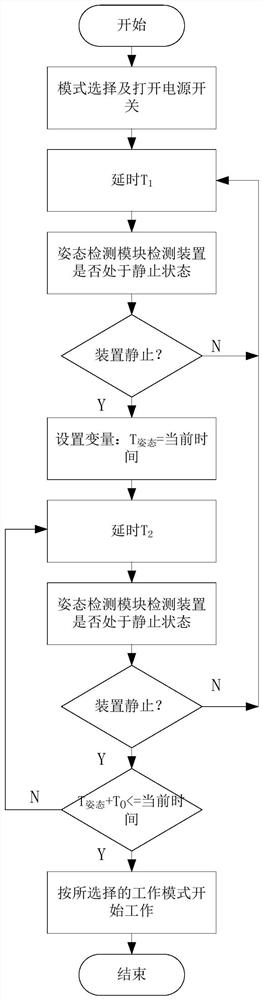
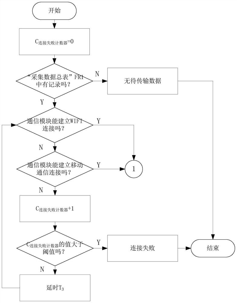
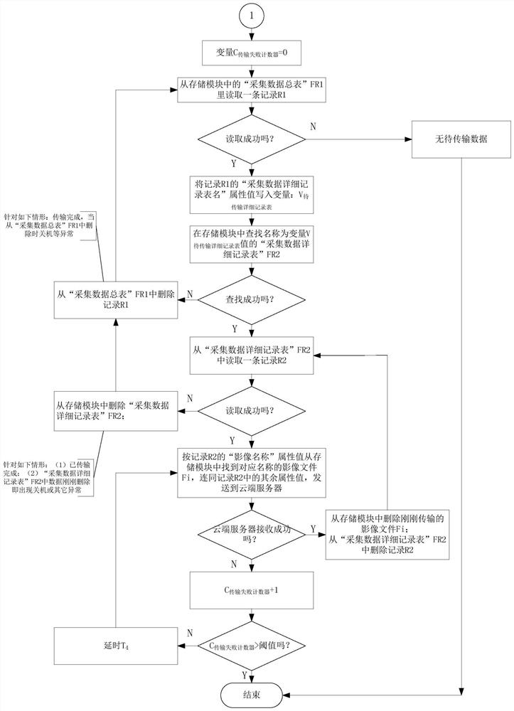
[0109] like Figure 1-8 Shown: a working method of an RIFA intelligent trapping device, which dynamically maintains a collection data general table and zero or more collection data detailed record tables in a storage module. Collected data detailed record table, the table name is named after 12 digits, the format: 2 digits of year + 2 digits of month + 2 digits of day + 2 digits of hour + 2 digits of minute + 2 digits of second; attributes: date and time, location, temperature and humidity, Lighting, image file name, image type (including two types of environmental image and trapping image); the general table of collected data, the table name is fixed, and the attribute: the name of the detailed record of the collected data.
[0110] The RIFA intelligent trapping device is provided with three working modes of collection, transmission and automatic, and selection and switching are carried out through the mode switching switch. In the acquisition mode, the device only performs data acquisition; in the transmission mode, the device only performs the transmission of the acquired data; in the automatic mode, the device transmits the acquired data in real time, During the transmission process, the transmission quality will be automatically judged, and if the number of transmission failures exceeds the threshold, it will automatically switch to a single acquisition process; after the acquisition process ends, the single transmission process will continue.
[0111] The specific steps are:
[0112] S1: Select the working mode through the mode switch, specifically acquisition mode, data transmission mode and automatic mode;
[0113] S2: Delay T 1;
[0114] S3: Whether the attitude detection module detects whether the device is in a static state, if it is a static state, go to step S4, otherwise go to step S2;
[0115] S4: Set variable T 姿态 equal to the current time;
[0116] S5: Delay T 2;
[0117] S6: Whether the posture detection module detects whether the device is in a static state, if it is a static state, go to step S7, otherwise go to step S2;
[0118] S7: Judgment T 姿态 +T 0 Whether it is less than or equal to the current time, if yes, go to step S8, otherwise go to step S5, where T 0 is the preset continuous stationary time of the device;
[0119] S8: Start data collection and data transmission according to the working mode selected in step S1.
[0120] The specific methods of the data transmission mode are:
[0121] S101: Counter variable C 连接失败计数器 initialized to 0;
[0122] S102: Determine whether the collection data summary table FR1 in the data module has a record, if so, go to step S103; otherwise, it is prompted by the light group that there is no data to be transmitted, and then go to step S1021;
[0123] S103: Determine whether the communication module can establish a Wifi connection with the cloud server, if yes, go to step S107; otherwise, go to step S104;
[0124] S104: Determine whether the communication module can establish a mobile communication connection with the cloud server, if yes, go to step S107; otherwise, go to step S105;
[0125] S105: Counter variable C 连接失败计数器 add 1;
[0126] S106: Judge the counter variable C 连接失败计数器 Whether the value is greater than the threshold, if it is greater than the light group prompts the connection failure, go to step S1021; otherwise delay T 3 Then go to step S103;
[0127] S107: Counter variable C 传输失败计数器 initialized to 0;
[0128] S108: Read a record R1 from the collection data summary table FR1 in the storage module;
[0129] S109: Determine whether the record R1 is successfully read, and if the read is successful, go to step S1010; otherwise, it is prompted by the light group that there is no data to be transmitted, and then go to step S1021;
[0130] S1010: Write the collected data detail record table name attribute value of record R1 into variable V 待传输详细记录表;
[0131] S1011: Find a variable named V in the storage module 待传输详细记录表 The collected data of the value is detailed record table FR2;
[0132] S1012: Determine whether the search of the collected data detailed record table FR2 is successful, and if successful, go to step S1013; otherwise, go to step S1014;
[0133] S1013: Read a record R2 from the collected data detailed record table FR2, and go to step S1015;
[0134] S1014: delete the record R1 from the collected data summary table FR1, and go to step S108;
[0135] S1015: Determine whether the record R2 is successfully read, if successful, go to step S1017; otherwise, go to step S1016;
[0136] S1016: delete the collection data detailed record table FR2 from the storage module, and go to step S1014;
[0137] S1017: Find the image file Fi with the corresponding name from the storage module according to the image name attribute value of the record R2, and send it to the cloud server together with the rest of the attribute values ​​in the record R2;
[0138] S1018: Determine whether the cloud server receives the data in step S1017 successfully, if successful, delete the image file Fi just transmitted from the storage module, delete the record R2 from the collected data detailed record table FR2, and go to step S1013; otherwise, go to step S1019 ;
[0139] S1019: Counter variable C 传输失败计数器 add 1;
[0140] S1020: Judgment variable C 传输失败计数器 Whether the value exceeds the threshold, if so, go to step S1021; otherwise, delay T 4 , go to step S1017;
[0141] S1021: The transmission work ends.
[0142] The collection mode is as follows:
[0143] S201: Set variable T 采集开始时间 is the current time; C 环境影像计数器 is 0; T 当次采集开始时间 The value is the current time; create a collection data detailed record table FR2 with the current time as the name in the data storage module; write record R1 into the collection data summary table FR1, and the collection data detailed record table name attribute value of R1 is the name of FR2 ;
[0144] S202: Send a data collection instruction to the environmental image acquisition module and the location module; the environmental image acquisition module starts to work, collects an environmental image Fi_0, and uses T 当次采集开始时间 The value is named with the suffix _0 and saved to the data storage module; the collected location, image type, value: environmental image, environmental image Fi_0 file name, T 当次采集开始时间 And the device number is written into the collected data detailed record table FR2 in the form of records; C 环境影像计数器 The value of is accumulated by 1;
[0145] S203: Send a fill light instruction to the fill light module; the fill light module turns on the fill light, and the fill light delay time is T 5;
[0146] S204: Send a data collection instruction to the trapping image collection module, location module, photosensitive module, and temperature and humidity module;
[0147] S205: Set variable T 当次采集开始时间 is the current time;
[0148] S206: The trapping image acquisition module starts to work, and collects a trapping area image Fi_1, with T当次采集开始时间 The value is named with the suffix _1, and is saved in the data storage module;
[0149] S207: The collected location, image type, value: trapping image, illuminance, temperature and humidity, trapping area image Fi_1 file name, T 当次采集开始时间 And the device number is written into the collected data detailed record table FR2 in the form of records;
[0150] S208: Judgment variable T 采集开始时间 with T 6 Whether the sum is less than or equal to the current time, if so, go to step S2013, otherwise go to step S209;
[0151] S209: Judgment variable C 环境影像计数器 Whether the value of is greater than the threshold, if so, delay T 7 Then go to step S203; otherwise go to step S2010;
[0152] S2010: Generate random numbers;
[0153] S2011: Determine whether the random number generated in step S2010 is within the agreed collection range, and if so, execute step S2012, otherwise delay T 7 Then go to step S203;
[0154] S2012: Send a data collection instruction to the environmental image acquisition module and the location module; the environmental image acquisition module starts to work, collects an environmental image Fi_0, and uses T 当次采集开始时间 The value is named with the suffix _0 and saved to the data storage module; the collected location, image type, value: environmental image, environmental image Fi_0 file name, T 当次采集开始时间 and the device number are written into the collected data detailed record table FR2 in the form of records, variable C 环境影像计数器 The value of 1 is accumulated; delay T 9 Then go to step S203;
[0155] S2013: Send a data collection instruction to the environmental image acquisition module and the location module; the environmental image acquisition module starts to work, collects an environmental image Fi_0, and uses T 当次采集开始时间 The value is named with the suffix _0 and saved to the data storage module; the collected location, image type, value: environmental image, environmental image Fi_0 file name, T 当次采集开始时间 And the device number is written into the collected data detailed record table FR2 in the form of records;
[0156] S2014: The collection work is over.
[0157] The automatic working mode is as follows:
[0158] S301: Set variable: T 采集开始时间 = current time, C 环境影像计数器 =0, variable V 传输标志 = true, C 传输失败计数器 =0, T 当次采集开始时间 = current time; create a detailed record table FR2 of the collected data with the name of the current time in the data storage module, and the name is written into the variable V at the same time 待传输详细记录表;Write record R1 into the collection data summary table FR1, and the collection data detailed record table name attribute value of R1 is the name of FR2;
[0159] S302: Send a data collection instruction to the environmental image acquisition module and the location module; the environmental image acquisition module starts to work, collects an environmental image Fi_0, and uses T 当次采集开始时间 The value is named with the suffix _0 and saved to the data storage module; the collected location, image type, value: environmental image, environmental image Fi_0 file name, T 当次采集开始时间 and the device number are written into the collected data detailed record table FR2 in the form of records, variable C 环境影像计数器 The value of is accumulated by 1;
[0160] S303: Initiate a data collection;
[0161] S304: Set variable T 采集间隔 is the current time;
[0162] S305: Judgment variable V 传输标志 Whether the value of is true, if so, go to step S306, otherwise go to step S308;
[0163] S306: initiate a data transmission;
[0164] S307: Judgment C 传输失败次数 Whether the value is greater than the threshold, if it is greater than set V 传输标志 is false, go to step S308; otherwise, go to step S308 directly;
[0165] S308: Judging variable T 采集间隔 add T 7 Whether it is less than or equal to the current time, if yes, go to step S309; ​​otherwise, go to step S3010;
[0166] S309: Judge T 采集开始时间 add T 6 Whether it is less than or equal to the current time, if yes, go to step S3011; otherwise, go to step S303;
[0167] S3010: Delay T 8 , go to step S308;
[0168] S3011: Set variable T 当次采集开始时间 The value of is the current time; send data collection instructions to the environmental image acquisition module and location module; the environmental image acquisition module starts to work, and collects an environmental image Fi_0, with T 当次采集开始时间 The value is named with the suffix 0 and saved to the data storage module; the collected location, image type, value: environmental image, environmental image Fi_0 file name, T 当次采集开始时间 And the device number is written into the collected data detailed record table FR2 in the form of records;
[0169] S3012: work according to the transmission mode;
[0170] S3013: The automatic working mode is finished.
[0171] The automatic working mode is as follows:
[0172] The step S303: initiating a data collection, specifically;
[0173] S3031: Send a fill light command to the fill light module;
[0174] S3032: The fill light module turns on the fill light, and the fill light delay time is T 5;
[0175] S3033: Send data collection instructions to the trapping image collection module, location module, photosensitive module, and temperature and humidity module;
[0176] S3034: Set variable T 当次采集开始时间 is the current time;
[0177] S3035: The trapping image acquisition module starts to work, and collects a trapping area image Fi_1, with T 当次采集开始时间 The value is named with the suffix _1, and is saved in the data storage module;
[0178] S3036: Location and image type to be collected, values: trapping image, illuminance, temperature and humidity, trapping area image Fi_1 file name, variable T 当次采集开始时间 The value and device number are written into the collected data detailed record table FR2 in the form of records;
[0179] S3037: Judgment variable C 环境影像计数器 Whether the value of is greater than the threshold, if so, go to step S30311; otherwise, go to step S3038;
[0180] S3038: Generate random numbers;
[0181] S3039: Whether the random number generated in step S3038 is within the agreed collection range, if so, go to step S30310, otherwise go to step S30311;
[0182] S30310: Send a data collection instruction to the environmental image acquisition module and the location module; the environmental image acquisition module starts to work, collects an environmental image Fi_0, and uses T 当次采集开始时间 The value is named with the suffix _0 and saved to the data storage module; the collected location, image type, value: environmental image, environmental image Fi_0 file name, T 当次采集开始时间 and the device number are written into the collected data detailed record table FR2 in the form of records, variable C 环境影像计数器 The value of is accumulated by 1;
[0183] S30311: A data collection activity ends.
[0184] The automatic working mode is as follows:
[0185] The step S306: initiate a data transmission, specifically;
[0186] S3061: Read a record R1 from the collection data summary table FR1 in the storage module;
[0187] S3062: Determine whether the record R1 is successfully read, and if the read is successful, go to step S3063; otherwise, go to step S3065;
[0188] S3063: Find the image file Fi with the corresponding name from the storage module according to the image name attribute value of the record R2, and send it to the cloud server together with the rest of the attribute values ​​in the record R2;
[0189] S3064: Determine whether the cloud server receives the data of step S3063 successfully, if successful, delete the image file Fi just transmitted from the storage module, delete the record R2 from the collected data detailed record table FR2, and go to step S3066; otherwise, go to step S3065 ;
[0190] S3065: Counter variable C 传输失败计数器 add 1;
[0191] S3066: One data transmission ends.
[0192] like Figure 9 and Figure 10 Shown: the device of the working method of the above-mentioned RIFA intelligent trapping device is provided with a device main body 1 and a trapping area cover 2, the longitudinal section of the device main body is in the shape of a zigzag, and a straight side of the device main body is the device bottom plate 3, The other straight side is the device top 4, the device bottom plate 3 and the device top 4 are connected through the first electrical installation cavity 5, and the trapping area cavity 6 is between the device bottom plate 3 and the device top 4; the device main body top 4 and the cross section of the bottom plate 3 is a lowercase n-shaped;
[0193] The inner surface of the bottom plate 3 of the main body of the device is provided with a bait placement groove 7;
[0194] A second electrical installation cavity 8 is provided on the upper surface of the top 4 of the device body;
[0195] The detachable cover on the trapping area cavity 6 is provided with a trapping area cover 2, and the bottom of the trapping area cover 2 is distributed with inlets and outlets 9, and the inlets and outlets 9 are comb-shaped inlets and outlets;
[0196] Two sides of the inner side of the first electrical installation cavity 5 are respectively provided with first sliding button grooves 10 , and both ends of the cover of the trapping area are respectively provided with second sliding button grooves 11 . A sliding button groove 10 is vertically slidably connected, wherein the second sliding button groove 11 is formed by curling the two ends of the cover of the trapping area.
[0197] A horizontal limiting groove 12 is provided on the edge of the upper surface of the bottom plate 3 of the device, and the horizontal limiting groove 12 cooperates with the bottom edge of the trapping area cover 2 to fix the bottom of the trapping area cover 2 .
[0198]A central controller is provided, and the collection end of the central controller is respectively connected with a photosensitive module, a temperature and humidity module, an attitude detection module and a power detection module; the image collection end of the central controller is respectively connected with an environmental image module and a trapping image module The control end of the central controller is connected with a light supplement module; the positioning end of the central controller is connected with a position module; the clock end of the central controller is connected with a clock module; the communication end of the central controller is connected with There is a communication module; the storage end of the central controller is connected with a data storage module; the photosensitive module is arranged on the top of the device main body 1 , and the temperature and humidity module is arranged on the side wall of the second electrical installation cavity 8 Above, the environmental image module is arranged on the outside of the second electrical installation cavity 8, and an image collection hole is opened on the side wall of the enclosure 2 of the trapping area, and the image collection hole is connected to the lens in the environmental image module. Matching; the trapping image module is arranged at the bottom of the second electrical installation cavity 8, and the trapping image module is facing the bait placement groove 7; the supplementary light module is arranged at the first electrical installation On the outer wall of the cavity 5 , the supplementary light module faces the cavity 6 in the trapping area.
[0199] After pulling the trapping area cover 2 upward, you can place baits such as ham sausage in the bait placement groove 7, and then put the trapping area cover 2 downward to seal the trapping area; the device main body 1 is controlled by the central Under the control of the device, the supplementary light control of the trapping area and the collection of image and picture data in the trapping area are completed. After the trapping activity is over, the trapping area cover 2 can be pulled upwards, so that the ants, dust, etc. in the trapping area can be easily cleaned.

PUM

no PUM

Description & Claims & Application Information

We can also present the details of the Description, Claims and Application information to help users get a comprehensive understanding of the technical details of the patent, such as background art, summary of invention, brief description of drawings, description of embodiments, and other original content. On the other hand, users can also determine the specific scope of protection of the technology through the list of claims; as well as understand the changes in the life cycle of the technology with the presentation of the patent timeline. Login to view more.

Similar technology patents

Body condition measuring device

InactiveUS20050234351A1simple structure
Owner:DENSO CORP

Magnetic cooling apparatus and control method thereof

ActiveUS20130180263A1simple structure
Owner:SAMSUNG ELECTRONICS CO LTD

Dual-Drivetrain of Power-Assist Vehicle

InactiveUS20100181130A1enhance uphill momentumsimple structure
Owner:CHOU WEN CHENG

Classification and recommendation of technical efficacy words

  • Simple structure
  • reduce volume

Sharing system for air-conditioning coat

InactiveCN107440179ASimple structureeasy to wear
Owner:QINGDAO HAIER AIR CONDITIONER GENERAL CORP LTD

Feeding device of sorter of batteries plate

InactiveCN101357717ASimple structurecooperate well
Owner:NANJING NORMAL UNIVERSITY

Emergency parachuting device and method for multiple-rotor unmanned aerial vehicle

InactiveCN103895870Aavoid aircraft crashSimple structure
Owner:SOUTH CHINA AGRI UNIV +1

Implant release mechanism

ActiveUS20080140178A1reduce volumereduce outer diameter
Owner:COOK MEDICAL TECH LLC

Speed reduction box for turbine fracturing

Owner:YANTAI JEREH PETROLEUM EQUIP & TECH

Miniature and Multi-Band RF Coil Design

ActiveUS20100090824A1reduce volumelong wavelength
Owner:HONG KONG APPLIED SCI & TECH RES INST

Automatic washing and dewatering combined device of rotary type mop

InactiveCN102370447Areduce volumeSimple structure
Owner:上海祥美网络科技有限公司 +1

Optical imaging system

ActiveUS20070008625A1reduce volumedeteriorate with time
Owner:SAMSUNG ELECTRONICS CO LTD
Why Eureka
Try Eureka