Anti-reflective film and display device
An anti-reflection film, high refractive index technology, used in instruments, optical components, coatings, etc., can solve the problem that the anti-reflection film cannot take into account the reflectivity and wear resistance at the same time
- Summary
- Abstract
- Description
- Claims
- Application Information
AI Technical Summary
Problems solved by technology
Method used
Image
Examples
preparation example Construction
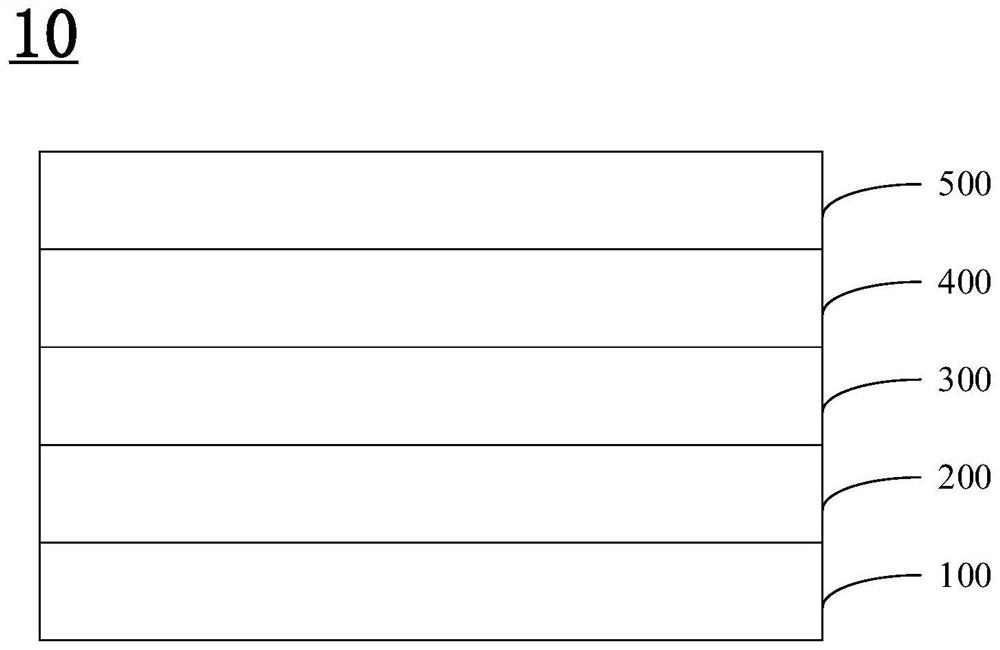
[0098] One embodiment of the present invention provides a method for preparing an antireflection film, comprising the following steps:
[0099] A hard coating, a high refractive index coating, a low refractive index coating, and an anti-fingerprint coating are sequentially formed on one side of the substrate.
[0100]In some examples, in the method for preparing the anti-reflection film, the step of forming the hard coating includes: coating the raw materials for the hard coating on the substrate and curing them.
[0101] In some examples, in the preparation method of the anti-reflection film, the step of forming the high-refractive-index coating includes: coating the raw material for preparing the high-refractive-index coating on the hardened coating and curing it.
[0102] In some examples, in the method for preparing the anti-reflection film, the step of forming the low-refractive-index coating includes: coating the raw material for the low-refractive-index coating on the h...
Embodiment 1
[0109] By weight percentage, the components of each layer of the antireflection film are as follows:
[0110] Substrate: PET (purchased from Toray, Japan, U483, thickness 50 μm);
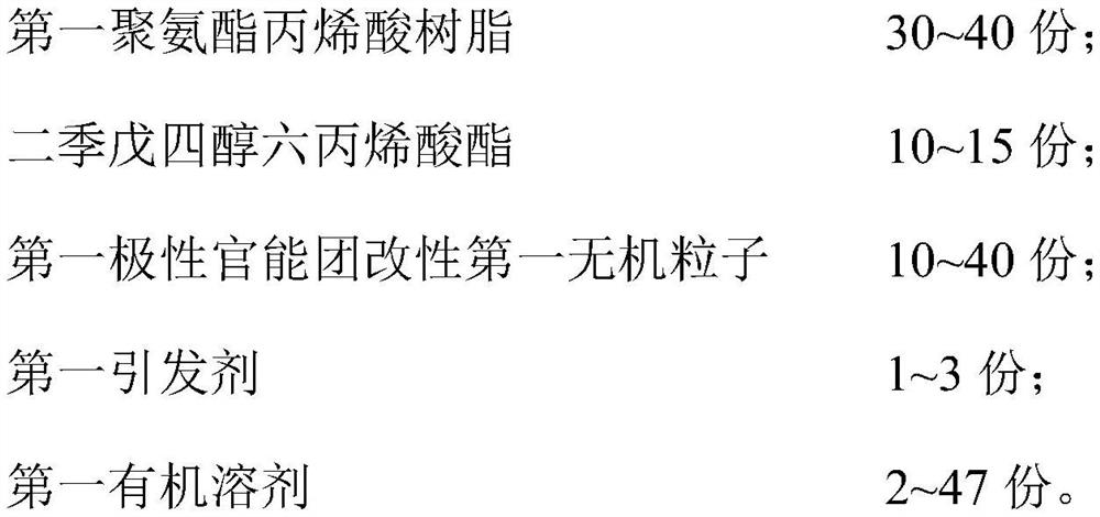
[0111] Thickness of hardened coating (4μm, surface dyne value 32): 30% polyurethane acrylic resin (functionality 9, glass transition temperature 35°C), dipentaerythritol hexaacrylate 10% (functionality 6), carboxyl Treated silica 10% (particle size 5nm), initiator 1-hydroxycyclohexyl phenyl ketone 3% and ethyl acetate 47%;
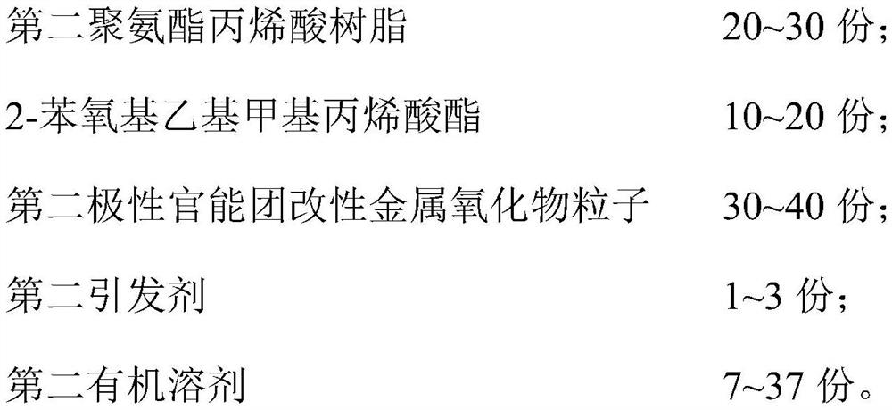
[0112] High refractive index coating (refractive index 1.6, thickness 80nm): polyurethane acrylic resin 20% (functionality 3), 2-phenoxyethyl methacrylate 20% (functionality 3), amino-treated Zirconia 40% (particle size 5nm), initiator 1-hydroxycyclohexyl phenyl ketone 3% and tetrahydrofuran 17%;
[0113] Low refractive index coating (refractive index 1.35, thickness 80nm): polyurethane acrylic resin 20% (functionality 9, glass transition temperature 35°C), dipentaerythritol h...
Embodiment 2
[0121] Basically the same as Example 1, the difference is that the components in the hardened coating are different, as follows:
[0122] Hard coating (thickness 4μm, surface dyne value 50): 30% polyurethane acrylic resin (functionality 9, glass transition temperature 35°C), dipentaerythritol hexaacrylate 10% (functionality 6), carboxyl Treated silica 40% (particle size 5 nm), initiator 1-hydroxycyclohexyl phenyl ketone 3% and acetone 17%.
PUM
| Property | Measurement | Unit |
|---|---|---|
| Thickness | aaaaa | aaaaa |
| Glass transition temperature | aaaaa | aaaaa |
| Particle size | aaaaa | aaaaa |
Abstract
Description
Claims
Application Information
 - R&D
- Intellectual Property
- Life Sciences
- Materials
- Tech Scout
- Unparalleled Data Quality
- Higher Quality Content
- 60% Fewer Hallucinations
Browse by: Latest US Patents, China's latest patents, Technical Efficacy Thesaurus, Application Domain, Technology Topic, Popular Technical Reports.
© 2025 PatSnap. All rights reserved.Legal|Privacy policy|Modern Slavery Act Transparency Statement|Sitemap|About US| Contact US: help@patsnap.com


