
High-gain intermediate-frequency amplifier with body leakage cross coupling technology

A cross-coupling, high-gain technology, applied in the field of high-gain intermediate-frequency amplifiers, can solve problems such as increasing the high-frequency gain of intermediate-frequency amplifiers, and achieve the effects of increasing voltage gain, reducing the problem of gain reduction with frequency, and improving high-frequency gain.

Pending Publication Date: 2022-05-17
UNIV OF ELECTRONIC SCI & TECH OF CHINA
View PDF3 Cites 0 Cited by
  • Summary
  • Abstract
  • Description
  • Claims
  • Application Information

AI Technical Summary

Problems solved by technology

[0013] The purpose of the present invention is to provide a high-gain intermediate frequency amplifier with body leakage cross-coupling technology for the problem that the high frequency gain of the existing intermediate frequency amplifier needs to be improved; the novel structure proposed by the invention adopts the body leakage cross coupling technology, without sacrificing Under the premise of output voltage swing and DC power consumption, the voltage gain of the intermediate frequency amplifier when processing MHz-level signals is effectively improved, and the high-frequency attenuation of the amplifier gain is effectively suppressed

Method used

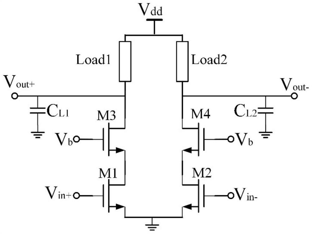

Image

  • High-gain intermediate-frequency amplifier with body leakage cross coupling technology
  • High-gain intermediate-frequency amplifier with body leakage cross coupling technology
  • High-gain intermediate-frequency amplifier with body leakage cross coupling technology

Examples


Embodiment Construction

[0032] The present invention will be described in further detail below in conjunction with the accompanying drawings and embodiments.

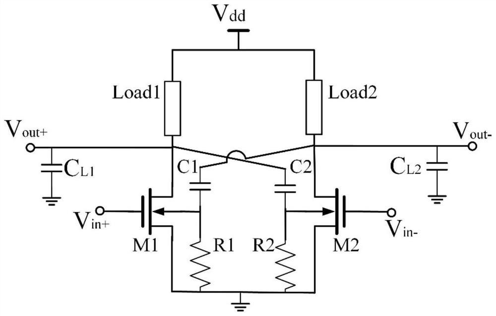
[0033] This embodiment proposes a high-gain IF amplifier with body-drain cross-coupling technology, which introduces body-drain cross-coupling capacitors on the basis of traditional common-source amplifiers, and connects the drains of MOS transistors on one side of the differential pair to the other through capacitors. The body electrode on one side, and at the same time provide a static bias for the body electrode through a resistor.

[0034] In this embodiment, NMOS is used as an input differential pair as an example, and its circuit schematic diagram is as follows image 3 shown; specifically include: MOS transistors M1 and M2, loads Load1 and Load2, load capacitance C L1 with C L2 , and coupling capacitors C1 and C2, bias resistors R1 and R2, where the gate of the MOS transistor M1 is connected to the positive input signal V in+ , the sou...


PUM


Abstract

The invention belongs to the technical field of wireless communication, and particularly provides a high-gain intermediate-frequency amplifier with a body leakage cross coupling technology, which is used for solving the problem that the high-frequency gain of the existing intermediate-frequency amplifier needs to be improved. The circuit is composed of two parts, wherein one part is a common-source differential amplifier composed of MOS tubes M1 and M2, loads Load1 and Load2 and load capacitors CL1 and CL2, and the other part is a body-drain cross coupling structure composed of coupling capacitors C1 and C2 and bias resistors R1 and R2. On the basis of a traditional common-source amplifier structure, a body-drain cross coupling technology is introduced, a drain electrode of an MOS tube on one side of a differential pair is connected to a body electrode of an MOS tube on the other side through a coupling capacitor, static bias is provided for the body electrode through a bias resistor, the high-frequency gain of the amplifier is effectively improved, and the high-frequency gain of the amplifier is improved. The problem that the gain is reduced along with the frequency due to large load capacitance is solved; in addition, output voltage swing and power consumption do not need to be sacrificed while the high-frequency gain is improved.

Description

technical field [0001] The invention belongs to the technical field of wireless communication, relates to a core module in a radio frequency receiving link: an intermediate frequency amplifier, and specifically provides a high-gain intermediate frequency amplifier with body leakage cross-coupling technology. Background technique [0002] As a key module in the radio frequency receiving chain, the intermediate frequency amplifier needs to amplify the voltage amplitude of the intermediate frequency signal obtained by down-conversion; in the radio frequency receiving chain, the gain of the intermediate frequency amplifier is high, which can not only suppress the noise of the subsequent stage, but also control the overall The noise figure of the link can also drive the ADC and other modules behind the link even when the input signal is small, improving the overall performance of the digital-to-analog link. In recent years, with the rapid development of wireless communication tec...

Claims


Application Information

Patent Timeline
IPC IPC(8): H03F3/45H03F1/08
CPCH03F3/45179H03F1/08H03F2200/75
Inventor 康凯刘润宇余益明吴韵秋赵晨曦刘辉华
Owner UNIV OF ELECTRONIC SCI & TECH OF CHINA
Learn More