Endoscope and thermal imaging combined detection device, method, equipment and medium

A detection device and detection method technology, applied in the field of endoscopy, can solve the problems of inconvenient carrying of the instrument, affecting the online function of diagnosis, and insufficient area of ​​the site, and achieve rich video data, convenient and fast maintenance, and diversified collection methods Effect

Inactive Publication Date: 2022-05-17
THINKCAR TECH CO LTD
View PDF6 Cites 0 Cited by
  • Summary
  • Abstract
  • Description
  • Claims
  • Application Information

AI Technical Summary

Problems solved by technology

[0003] For the existing technology, the endoscope uses the WI-FI transmission scheme to display the collected video data, that is, the data transmission is realized by connecting the diagnostic equipment (terminal) to the WI-FI module of the endoscope It shows that because the diagnostic equipment (terminal) is connected to the WI-FI module of the endoscope, network communication will not be possible, which will affect the online function of diagnosis. At the same time, the operation needs to be manually connected to the WI-FI module, which is more cumbersome.
[0004] Moreover, if the endoscope uses the camera module alone for shooting, the collected video data content will be single, and more screen content cannot be diagnosed. If the problem of single diagnostic data content is to be solved, other devices need to be used together, such as For thermal imaging equipment, multiple devices put into use at the same time will lead to insufficient space for the site. On the other hand, it is extremely inconvenient to carry multiple devices

Method used


Image

  • Endoscope and thermal imaging combined detection device, method, equipment and medium
  • Endoscope and thermal imaging combined detection device, method, equipment and medium
  • Endoscope and thermal imaging combined detection device, method, equipment and medium

Examples


Embodiment 1

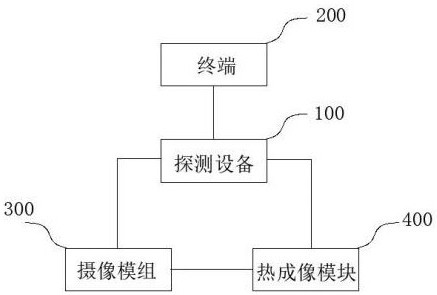
[0053] Such as figure 1 As shown, the present application proposes a detection device combining endoscope and thermal imaging. The detection device 100 is used to connect the terminal 200, the camera module 300 and the thermal imaging module 400. The detection device 100 includes an endoscope main board, The main board of the endoscope is integrated with a first communication interface and an adapter board, the first communication interface is externally connected to the terminal 200, and the adapter board is internally connected, and the first communication interface and the adapter board are connected according to the data wire electrical connection;

[0054] The adapter board is respectively connected to the camera module 300 and the thermal imaging module 300;

[0055] The thermal imaging module 400 is connected to the camera module 300;

[0056] The detection device 100 shoots according to the camera module 300, and collects video data;

[0057] And / or, shoot according...

Embodiment 2

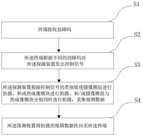
[0095] Such as figure 2 As shown, the present application also proposes a detection method combining endoscope and thermal imaging, which is applied to the detection device 100, the terminal 200, the camera module 300 and the thermal imaging module 400. The detection device 100 includes an endoscope main board, A first communication interface and an adapter board are integrated on the main board of the endoscope, and the first communication interface is externally connected to the terminal 200 and internally connected to the adapter board;

[0096] The adapter board is respectively connected to the camera module 300 and the thermal imaging module 400;

[0097] The thermal imaging module 400 is connected to the camera module 300;

[0098] The terminal 200 is provided with a control panel, buttons, and a fourth communication interface adapted to the first communication interface, and the first communication interface is electrically connected to the fourth communication interf...

Embodiment 3

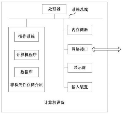
[0116] Such as image 3 As shown, the present application also provides a computer device, which may be a server, and its internal structure may be as follows image 3 shown. The computer device comprises a processor, a memory, a network interface and a database connected according to said system bus. Among them, the processor designed by the computer is used to provide calculation and control capabilities. The memory of the computer device includes a non-volatile storage medium and an internal memory. The non-volatile storage medium stores an operating system, computer programs and databases. The memory provides an environment for the operation of the operating system and computer programs in the non-volatile storage medium. The database of the computer equipment is used to store all data required by the process of the timing task scheduling method. The network interface of the computer device is used for communication with external terminals via the network connection. ...


PUM


Abstract

The invention discloses an endoscope and thermal imaging combined detection device, method, equipment and medium, and relates to the technical field of endoscopes, the detection device is used for connecting a terminal, a camera module and a thermal imaging module, the detection device comprises an endoscope mainboard, the endoscope mainboard is integrated with a first communication interface and an adapter plate, and the adapter plate is connected with the terminal. The first communication interface is externally connected with the terminal and internally connected with the adapter plate, the adapter plate is respectively connected with the camera module and the thermal imaging module, the thermal imaging module is connected with the camera module, and the detection device is used for detecting video data shot and collected by the camera module according to the video data shot and collected by the camera module; and/or, shooting according to the thermal imaging module, and collecting video data; and/or, according to the camera module and the thermal imaging module, shooting and video data acquisition are respectively carried out at the same time, and the video data are transmitted to the terminal, the detection device can realize video acquisition in multiple ways, and one device is more intelligent in function and full in experience feeling.

Description

technical field [0001] The present application relates to the technical field of endoscopes, in particular, to a detection device, method, equipment and medium for combining endoscopes with thermal imaging. Background technique [0002] At present, endoscopes have penetrated into many industries. From the perspective of application, they can be simply divided into two categories, one is used in the medical field, and the other is used in the industrial field. However, both work methods are used to collect video screen. [0003] For the existing technology, the endoscope uses the WI-FI transmission scheme to display the collected video data, that is, the data transmission is realized by connecting the diagnostic equipment (terminal) to the WI-FI module of the endoscope It shows that because the diagnostic equipment (terminal) is connected to the WI-FI module of the endoscope, network communication will not be possible, which will affect the online function of diagnosis. At t...

Claims


Application Information

Patent Timeline
Patent Type & Authority Applications(China)
IPC IPC(8): H04N5/225H04N5/33H04N7/18
CPCH04N5/33H04N7/181H04N23/555H04N23/50
Inventor 谭斌肖灵聪罗源
Owner THINKCAR TECH CO LTD
Why Eureka
Try Eureka