Tubular pile joint annular welding equipment capable of automatically identifying and compensating welding seam

An automatic identification and circular welding technology, which is applied in welding equipment, welding equipment, auxiliary welding equipment, etc., can solve the difficulties in quality control and standardized operation, bottlenecks in operation efficiency and construction quality, uneven level of welding workers, etc. problems, to ensure that the overall construction period is controllable, the weld quality is good and stable, and the effect of avoiding radiation

Inactive Publication Date: 2022-05-24
GUANGDONG PROVINCIAL CHANGDA HIGHWAY ENG
View PDF10 Cites 0 Cited by
  • Summary
  • Abstract
  • Description
  • Claims
  • Application Information

AI Technical Summary

Problems solved by technology

Traditional prestressed concrete pipe piles are mainly connected by manual welding. Affected by factors such as the environment and the welders themselves, omissions and mistakes will inevitably occur in manual operations. The level of welding workers is uneven, and it is difficult to guarantee the welding quality. Due to factors such as increasing shortage and rising labor costs, the efficiency and construction quality of pipe pile welding operations have reached a bottleneck
Moreover, manual welding is very dependent on personal experience, making it difficult to control quality and achieve standardized operations

Method used


Image

  • Tubular pile joint annular welding equipment capable of automatically identifying and compensating welding seam
  • Tubular pile joint annular welding equipment capable of automatically identifying and compensating welding seam
  • Tubular pile joint annular welding equipment capable of automatically identifying and compensating welding seam

Examples


Embodiment 1

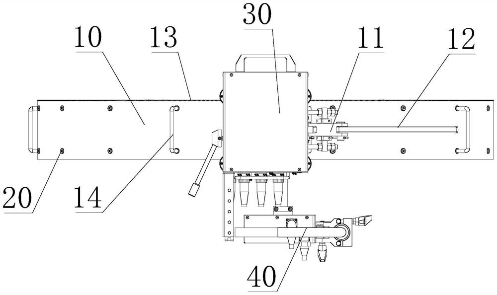
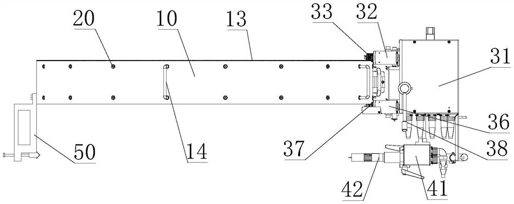
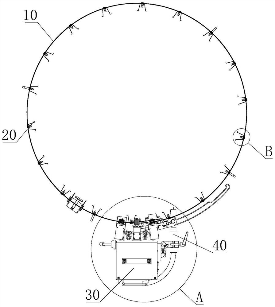
[0035] see Figure 1-Figure 3 As shown, the present invention is an annular welding equipment for pipe pile joints that automatically recognizes compensation welds, including steel belt guide rails 10. The steel belt guide rails 10 are connected into a ring structure by a quick latch 11. At the same time, the steel belt guide rail 10 is forced to bring pressure to the pipe pile, and the pipe pile is held tightly under the action of this pressure; a lock rod 12 is provided on the quick lock 11, and the lock rod 12 is of a circular arc structure, which can facilitate the rapid The latch 11 is unlocked and locked, and the arc-shaped structure does not restrict the movement of the drive assembly 30; a plurality of sets of guide rail handles 14 are evenly arranged on the outer circumference of the steel belt guide rail 10, which is convenient for the rapid operation of the steel belt guide rail 10. installation, so as to further improve the efficiency of welding of pipe piles.

[...

Embodiment 2

[0049] The structure of this embodiment is the same as that of the first embodiment, and the difference is:

[0050] see Figure 7 and Figure 8 As shown, the snap-fit ​​assembly 20 includes an adjusting bolt 24 threadedly connected to the steel belt guide 10. The inner side wall of the steel belt guide 10 is provided with a threaded sleeve 25 which is matched with the adjusting bolt 24. The setting of the threaded sleeve 25 is convenient for adjusting the bolt. 24 to precisely adjust the position of the second U-shaped card board 26; the end of the adjusting bolt 24 located on the inner side of the steel belt guide 10 is rotated and installed with the second U-shaped card plate 26, and the second U-shaped card plate 26 is fixedly provided with a connecting sleeve 27 and adjustment The ends of the bolts 24 are rotated and connected to ensure that when the adjusting bolts 24 adjust the position of the second U-shaped clamping plate 26, the second U-shaped clamping plate 26 wil...

Embodiment 3

[0053] The structure of this embodiment is the same as that of the second embodiment, and the difference is:

[0054] see Figure 9 As shown, a cooling bracket 60 is detachably installed on the side end of the drive assembly 30, and a cooling fan 61 is fixedly installed on the cooling bracket 60. The cooling fan 61 is provided to rapidly cool the welded seam, thereby reducing the cooling time of welding, and further Improve the efficiency of welding construction of pipe piles.

[0055] In the specific implementation process of the present invention, the specific steps are:

[0056] Step 1. Confirm the consumables required for welding;

[0057] Lincoln Electric solid core 1.2mm welding wire, model JM4-56, follow the wire feeder installation steps to complete the wire installation and check whether the wire feeding is smooth:

[0058] Mix protective gas, ammonia 80%, carbon dioxide 20%, specification: 40L, pressure 5Mpa, install and connect the trachea joint, open the gas val...


PUM


Abstract

The invention discloses tubular pile joint annular welding equipment capable of automatically identifying and compensating welding seams, which comprises a steel belt guide rail, the steel belt guide rail is connected into an annular structure through a quick clamping lock, a plurality of groups of clamping components are mounted on the steel belt guide rail, and the clamping components are used for clamping and connecting the steel belt guide rail to a tubular pile joint; a driving assembly is installed on the steel belt guide rail and annularly moves along the steel belt guide rail, and a welding assembly used for welding a pipe pile connector is installed at the lower end of the driving assembly. By means of the method, pipe pile welding work can be completed quickly and efficiently, the welding time is shortened by 50%, it is ensured that the whole construction period is controllable, wrap angle welding and multi-layer and multi-pass welding can be achieved through welding program control, and it is ensured that the welding process is controllable and the welding seam quality is good and stable.

Description

technical field [0001] The invention relates to the technical field of large-diameter bridge prefabricated pipe pile foundation construction, in particular to an annular welding device for pipe pile joints capable of automatically identifying compensation welds. Background technique [0002] In the process of bridge construction, the pile-beam integrated machine is widely used for construction, and the technology of integrating piling and beam erection without landing construction is more and more common. In order to meet the load and deformation control requirements of the upper structure of the bridge, multi-section pipe piles are usually connected. To improve the bearing capacity of the pile foundation. The traditional prestressed concrete pipe piles are mainly connected by manual welding. Affected by factors such as the environment and the welders themselves, omissions and mistakes will inevitably occur in manual operations. The level of welders is uneven, and it is diff...

Claims


Application Information

Patent Timeline
Patent Type & Authority Applications(China)
IPC IPC(8): B23K31/02B23K37/00B23K37/02
CPCB23K31/02B23K37/00B23K37/0211B23K37/0247
Inventor 邓文豪杨兴义林文朴林超黄巧敏张松
Owner GUANGDONG PROVINCIAL CHANGDA HIGHWAY ENG
Why Eureka
Try Eureka