Compressed air energy storage power generation system-based phase modifier system and operation method thereof

A technology for compressed air energy storage and power generation systems, applied in the field of camera control systems, can solve problems such as underutilization, and achieve the effects of improving insufficient support capacity, reducing network loss, and improving voltage stability.

Pending Publication Date: 2022-05-24
CEEC JIANGSU ELECTRIC POWER DESIGN INST
View PDF2 Cites 0 Cited by
  • Summary
  • Abstract
  • Description
  • Claims
  • Application Information

AI Technical Summary

Problems solved by technology

Therefore, the compressed air energy storage power station has the characteristics of intermittent operation, the expansion side only operates during the energy release process, and the turbine and generator are in the cranking state during the non-energy release phase, which is not fully utilized

Method used


Image

  • Compressed air energy storage power generation system-based phase modifier system and operation method thereof

Examples


Embodiment 1

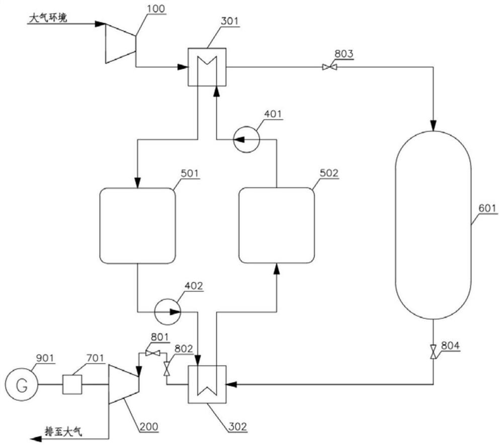
[0051] like figure 1 As shown, a phase modulation system based on a compressed air energy storage power generation system includes a compression subsystem, a cooling and heating cycle subsystem, an expansion subsystem, a gas storage 601, a hydraulic coupler 701, a generator 901, and a regulating valve 801 ; Block valve A802, block valve B 803 and block valve C 804. The compression subsystem includes a compressor 100 and a compression side heat exchanger 301 . The expansion subsystem includes a turbine 200 and an expansion side heat exchanger 302 . The cold and heat cycle subsystem includes a low temperature side circulating water pump 401 , a high temperature side circulating water pump 402 , a high temperature heat storage tank 501 and a low temperature heat storage tank 502 .

[0052] The compression side heat exchanger 301 and the expansion side heat exchanger 302 use a horizontal shell-and-tube radiator, the circulating working fluid on the shell side of the heat exchang...

Embodiment 2

[0060] A method for operating a phase modulation system based on a compressed air energy storage power generation system based on Embodiment 1, comprising:

[0061] The compression subsystem and gas storage 610 provide high pressure gas for the expansion subsystem;

[0062] The expansion subsystem uses high-pressure air as the working medium, adjusts the rotational speed of the generator 901, and delivers reactive power to the grid.

[0063] The specific operation methods include:

[0064] Operation mode 1, when the generator 901 enters the phase modulation condition from the cranking condition:

[0065] Gradually open the regulating valve 801 in front of the turbine 200, so that the turbine 200 drives the generator 901 to run. When the speed of the generator 901 reaches 3000 rpm, the generator 901 is connected to the grid at the same time. Provide reactive power; adjust the hydraulic coupling 701 to disconnect the generator 901 from the turbine 200, gradually close the regu...


PUM


Abstract

The invention discloses a phase modifier system based on a compressed air energy storage power generation system and an operation method of the phase modifier system. The system comprises a compression subsystem, an expansion subsystem, a gas storage, a hydraulic coupler and a power generator. The compression subsystem comprises a compressor and a compression side heat exchanger, the compressor sucks air for compression to obtain high-pressure gas, and the high-pressure gas is input into the compression side heat exchanger for cooling and then input into the gas storage; the expansion subsystem comprises a turbine and an expansion side heat exchanger, high-pressure gas stored in the gas storage is input into the turbine after being input into the expansion side heat exchanger to be heated, the high-temperature and high-pressure gas enters the turbine to do work through expansion, an output shaft of the turbine is connected with the input end of the hydraulic coupler, and the output end of the hydraulic coupler is connected with the input end of the generator. The phenomenon that the reactive power supporting capacity of a power grid is insufficient can be improved, the original power generation function of a unit can be reserved, and the function of a phase modifier can be achieved.

Description

technical field [0001] The invention relates to a phase regulating system based on a compressed air energy storage power generation system and an operation method thereof, belonging to the technical field of compressed air energy storage systems. Background technique [0002] In modern power systems, most of the loads (such as motors, transformers, etc.) are inductive loads, and inductive (lag) reactive power must be absorbed from the power supply or grid, resulting in increased excitation loss of generators, reduced output, and reduced transmission lines. Transmission capacity, reduce transmission quality and increase transmission loss. Therefore, capacitive reactive power equipment must be installed in the transmission line to compensate inductive reactive power with capacitive reactive power. In the long-distance high-voltage transmission system, the capacitive reactive power generated by the capacitance of the transmission line to the ground is very large, which may be ...

Claims


Application Information

Patent Timeline
Patent Type & Authority Applications(China)
IPC IPC(8): F01K13/00F01K3/00F01K3/12F01K25/08F01D15/10F04B39/06F04B41/02
CPCF01K13/00F01K3/00F01K3/12F01K25/08F01D15/10F04B41/02F04B39/06Y02E60/16
Inventor 凌晨宋坤林吴斌李季朱学成李睿翁海峰邹晗孙宇殷佳尉
Owner CEEC JIANGSU ELECTRIC POWER DESIGN INST
Why Eureka
Try Eureka