Static focusing glass nanosecond laser punching system and punching method
A laser cutting and glass technology, applied in glass production, laser welding equipment, welding/welding/cutting items, etc., can solve the problems of poor quality of glass cutting holes, low cutting efficiency, difficulty in laser cutting of 6-15mm thick glass, etc. , achieve the effect of good cutting quality, high hole forming rate, and solve the difficulty of laser cutting
- Summary
- Abstract
- Description
- Claims
- Application Information
AI Technical Summary
Problems solved by technology
Method used
Image
Examples
Embodiment 1
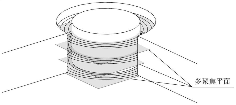
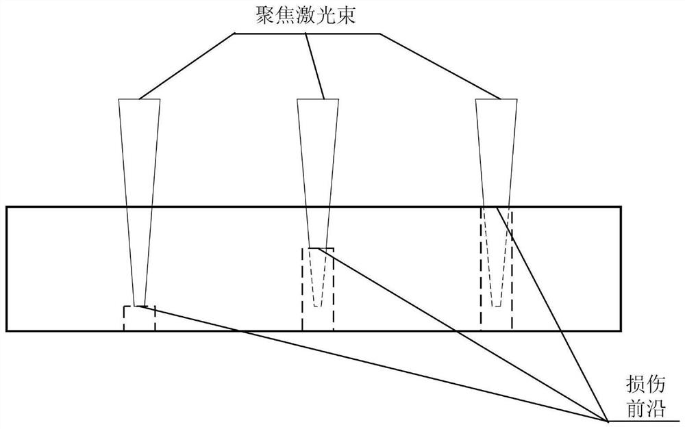
[0036] like Figure 2-Figure 6 As shown, this embodiment proposes a statically focused glass nanosecond laser hole cutting system, including a laser 10, a collimating beam expander 20, a reflecting mirror 30, a 2D digital galvanometer and The control board 40, the focusing field lens 50 and the dynamic focusing device 60, wherein the laser 10 is used to emit laser pulses, and the laser pulse width is less than 10ns; the collimating beam expander 20 is used to adjust the laser beam diameter and beam collimation; The mirror 30 is used to guide the laser beam emitted by the laser 10 into the digital galvanometer; the 2D digital galvanometer and the control board 40 are used to control the high-precision high-speed scanning of the laser beam in the xy plane; the focusing field mirror 50 is used for High-quality focusing and vertical incidence of laser beams within a certain width; dynamic focusing device 60 for precise positioning and movement of the focusing plane in the directio...
Embodiment 2
[0042]This embodiment proposes a statically focused glass nanosecond laser hole cutting method. Using the statically focused glass nanosecond laser hole cutting system in Example 1, the laser beam emitted by the laser 10 is collimated and expanded by a collimating beam expander 20. The beam and the mirror 30 are imported into the 2D digital galvanometer and the 2D digital galvanometer in the control board 40, and under the control of the control board and software, the scanning is repeated according to a predetermined trajectory, and the scanning laser beam is focused on the glass workpiece through the focusing field lens 50. In addition, the focusing plane remains static during the scanning process. During the scanning process of the focused laser beam, the glass material is eroded and a slit is formed, and the slit is penetrated to form a slit.
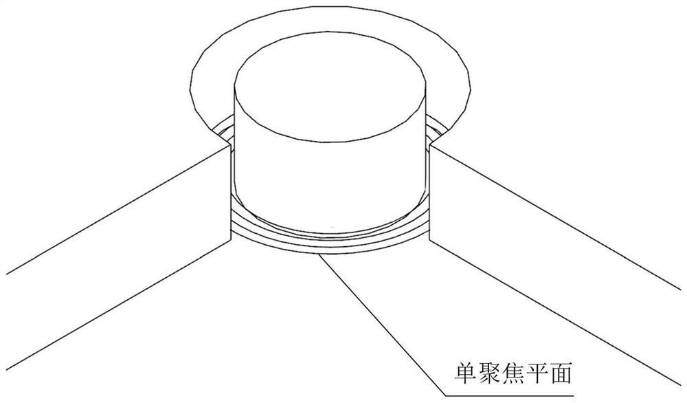
[0043] like figure 2 , image 3 As shown, when the glass with a thickness of less than 2 mm is processed by a statically focused...
Embodiment 3
[0049] When using the statically focused glass nanosecond laser cutting method to process glass with a thickness of less than 2mm, the specific steps are as follows:
[0050] First, the glass with a thickness of 2 mm or less is fixed on the processing platform, and the laser 10 is activated to emit a laser beam.
[0051] Then, the laser beam first adjusts the beam diameter and collimation through the collimating beam expander 20, and then guides the beam to the 2D digital galvanometer and the 2D digital galvanometer in the control board 40 through the high-power mirror 30, while the control board The card controls the beam to scan repeatedly according to a predetermined trajectory in the xy plane; in this embodiment, the scanning parameters include that the frequency of the laser 10 is 100-200 kHz, and the scanning speed is 3000-5000 mm / s.
[0052] Finally, the focusing field lens 50 focuses the emitted laser beam with high quality and is vertically incident on the glass workp...
PUM
| Property | Measurement | Unit |
|---|---|---|
| wavelength | aaaaa | aaaaa |
| power | aaaaa | aaaaa |
| length | aaaaa | aaaaa |
Abstract
Description
Claims
Application Information
 - R&D
- Intellectual Property
- Life Sciences
- Materials
- Tech Scout
- Unparalleled Data Quality
- Higher Quality Content
- 60% Fewer Hallucinations
Browse by: Latest US Patents, China's latest patents, Technical Efficacy Thesaurus, Application Domain, Technology Topic, Popular Technical Reports.
© 2025 PatSnap. All rights reserved.Legal|Privacy policy|Modern Slavery Act Transparency Statement|Sitemap|About US| Contact US: help@patsnap.com


