Soil-squeezing hole-forming and pile-forming method for threaded pile

A threaded pile and hole-forming technology, which is applied in the direction of drilling equipment and methods, earth drilling, and sheet pile walls, can solve the problems of reduced shear resistance of the soil around the pile and large fluctuations in the bearing capacity of the threaded pile, and achieve high bearing capacity. , fully squeezed soil, and high bonding strength

Pending Publication Date: 2022-05-27
刘帅
View PDF0 Cites 0 Cited by
  • Summary
  • Abstract
  • Description
  • Claims
  • Application Information

AI Technical Summary

Problems solved by technology

In the existing threaded pile construction, threaded drilling tools with equal pitch are used, and the power head pile driver with high torque is used to realize it through synchronous control technology. Due to the processing and manufacturing accuracy of threaded drilling tools, the rated output torque of Controlling the influence of various factors such as technical precision and geological conditions, the bearing capacity of threaded piles formed by construction fluctuates greatly, especially the soil around piles with complex geological conditions, such as containing hard interlayers, the fluctuations are more obvious. The main reason is that When the soil is squeezed into a threaded hole, the soil between the threaded teeth and the surrounding soil will be disturbed, and then the pile will be formed by reverse synchronous lifting and filling, and the shear capacity of the pile surrounding the soil will be reduced.

Method used


Image

  • Soil-squeezing hole-forming and pile-forming method for threaded pile
  • Soil-squeezing hole-forming and pile-forming method for threaded pile
  • Soil-squeezing hole-forming and pile-forming method for threaded pile

Examples


Embodiment Construction

[0031] Example Threaded piles squeezed soil to form holes and pile-forming methods

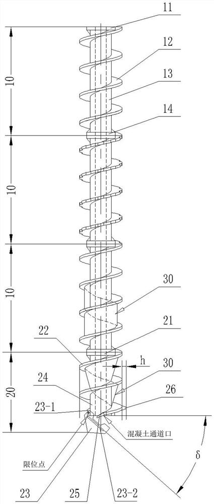
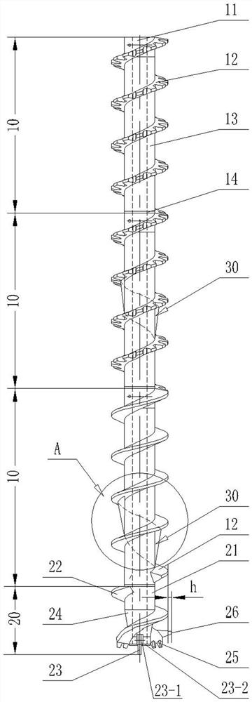
[0032] like Figure 1-Figure 4 As shown, a soil extruding drilling tool with a screw extruding soil body comprises a drill pipe (10) and a drill bit (20).

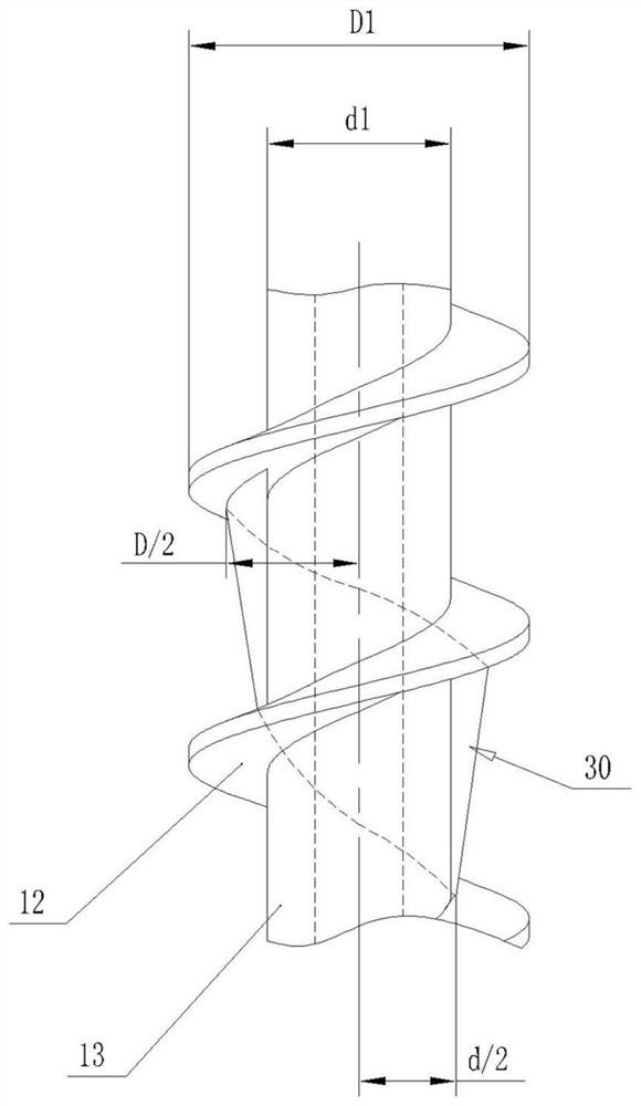
[0033] The drill pipe (10) can be connected in series with one or more sections. The drill pipe (10) includes a joint I (11), a helical blade I (12), a core pipe I (13) and a joint II (14). The joint I (11) and the joint II (14) are respectively coaxially fixed on both ends of the core pipe I (13) and integrated with the core pipe I (13). The helical blade I (12) is helically wound on the outer surfaces of the joint I (11), the core pipe I (13) and the joint II (14). The inner cavity of the drill pipe (10) is a channel for the concrete to pass through. The joint I (11) and the joint II (14) can be hexagonal (or octagonal) joints with internal and external inlay matching, and can also be a combination of flange positioning and matching. ...


PUM


Abstract

The invention relates to a soil-squeezing hole-forming and pile-forming method for a threaded pile. A soil squeezing drilling tool with a spiral soil squeezing body is utilized, and the method comprises the following steps that in a soil squeezing hole forming process, a soil body uploading channel is narrowed through the spiral soil squeezing body, normal uploading of a soil body is hindered, part of retention is formed, and the retained soil body is forced to fill a groove in the pile hole wall; in the pile forming process, the upper interface of concrete in a pile body hole is always kept 1.0-1.3 m higher than the bottom end of a soil squeezing drilling tool in the drill lifting and concrete pouring process, a diameter expanding block buried in the concrete is squeezed into a spiral groove in the pile hole wall, the spiral groove is opposite to the drilling rotation direction, and concrete is poured into the groove and the column body pile body hole together. And the rotating soil squeezing drilling tool and the pressure grouting concrete continue to be lifted till the pile top elevation is reached. The method has the advantages that the threaded holes are formed through soil squeezing reasonably, and the bearing capacity of the pile formed through pressure irrigation is higher.

Description

technical field [0001] The invention belongs to the technical field of building pile construction, and particularly relates to a threaded pile extruding soil to form a hole and a pile forming method. Background technique [0002] Threaded piles have strong advantages in cast-in-place concrete piles. It converts the soil-pile friction due to the stress between the traditional pile and soil into the shear between soil and soil, and increases the lateral resistance of the pile by 1.3-2.0 times, and contributed to the promotion of energy-saving and emission-reduction building pile foundations. In the existing threaded pile construction, threaded drilling tools with equal pitch are used, and high-torque power head pile drivers are used to achieve through synchronous control technology. Due to the influence of various factors such as control technology accuracy and geological conditions, the bearing capacity of threaded piles formed by construction fluctuates greatly, especially ...

Claims


Application Information

Patent Timeline
Patent Type & Authority Applications(China)
IPC IPC(8): E02D5/34E02D15/04E02D5/56E02D5/44E02D7/00E21B7/26E21B7/28E21B10/26E21B10/43E21B10/44E21B10/60E21B10/62E21B12/00E21B17/22
CPCE02D5/34E02D15/04E02D5/56E02D5/44E02D7/00E21B7/28E21B7/26E21B17/22E21B10/43E21B10/44E21B10/26E21B10/602E21B10/62E21B12/00
Inventor 刘帅夏日光
Owner 刘帅
Why Eureka
Try Eureka