
High-thermal-conductivity silicon carbide substrate laser

A silicon carbide substrate and laser technology, which is applied in the direction of semiconductor lasers, lasers, laser components, etc., can solve the problems of affecting the working stability of lasers, reducing the service life of chips, and poor heat dissipation performance of chips, so as to improve working stability, The effect of prolonging the service life and improving the heat dissipation performance

Pending Publication Date: 2022-05-27
益阳曙光沐阳电子技术有限公司
View PDF0 Cites 0 Cited by
  • Summary
  • Abstract
  • Description
  • Claims
  • Application Information

AI Technical Summary

Problems solved by technology

[0002] A laser is a device capable of emitting laser light. The semiconductor laser chip is the cornerstone and source of the entire laser processing industry chain. It is the key core component of laser pumping, industrial processing and advanced manufacturing. It can be widely used in advanced manufacturing, medical cosmetology, aerospace, safety protection and other fields. At the same time, the existing laser chip has poor heat dissipation performance. During the working process of the laser, it is easy to burn due to overheating. Cause damage, thereby reducing the service life of the chip, and most of the external connectors of the laser are welded to the internal circuit by welding. The shock and vibration generated during use are likely to cause loose connections, which affects the working stability of the laser. Therefore, It is necessary to design a silicon carbide substrate laser with high thermal conductivity

Method used


Image

  • High-thermal-conductivity silicon carbide substrate laser
  • High-thermal-conductivity silicon carbide substrate laser
  • High-thermal-conductivity silicon carbide substrate laser

Examples


Embodiment Construction

[0019] The technical solutions in the embodiments of the present invention will be clearly and completely described below with reference to the accompanying drawings in the embodiments of the present invention. Obviously, the described embodiments are only a part of the embodiments of the present invention, rather than all the embodiments. Based on the embodiments of the present invention, all other embodiments obtained by those of ordinary skill in the art without creative efforts shall fall within the protection scope of the present invention.

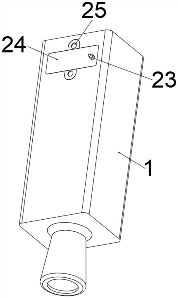
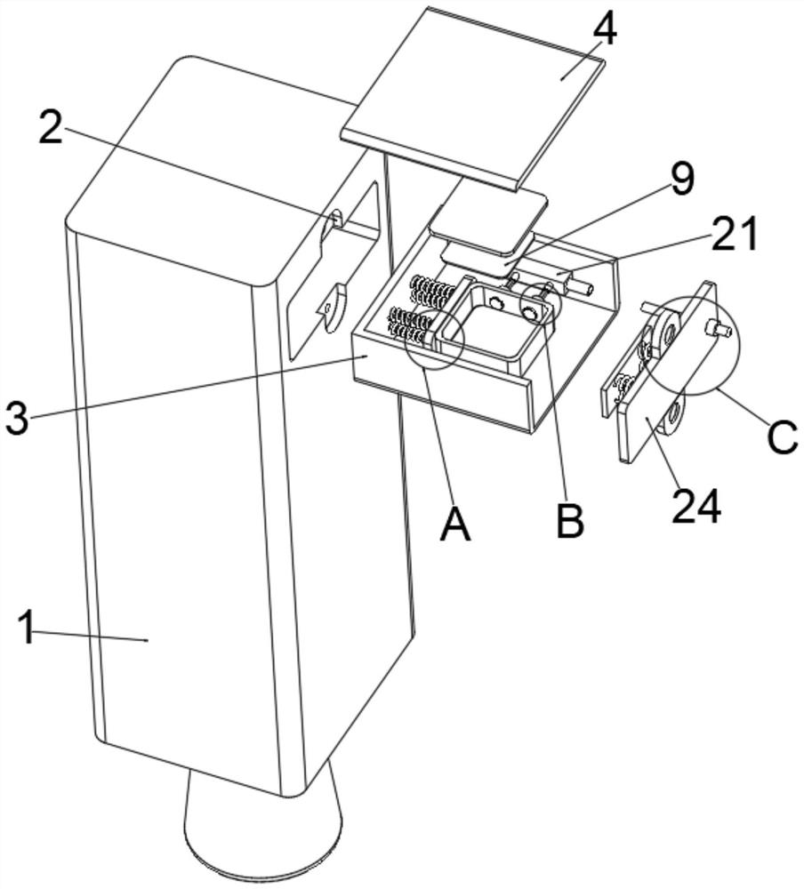
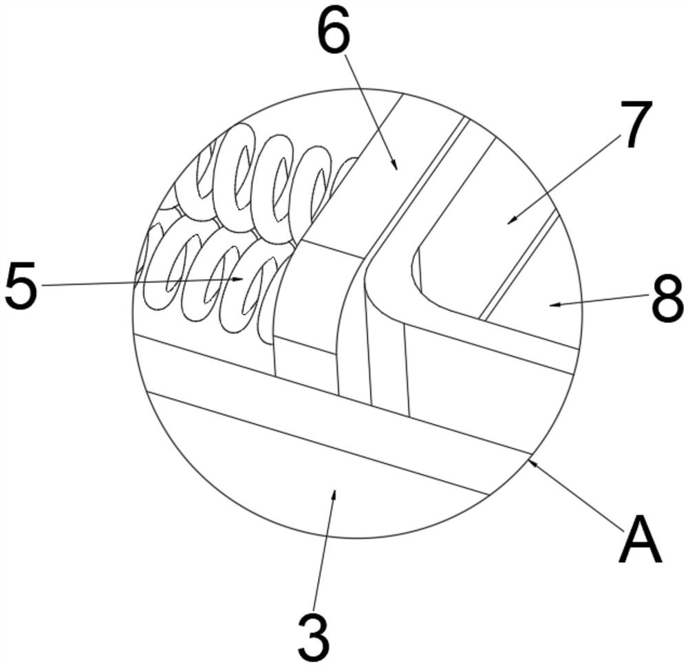
[0020] see Figure 1-7 , the present invention provides a technical solution: a silicon carbide substrate laser with high thermal conductivity, comprising a laser body 1, a mounting shell 3 and a laser chip 15, a limiting slot 2 is provided on the top of one side of the laser body 1, and the laser body 1 The mounting shell 3 is embedded in the middle, the top of the mounting shell 3 is provided with a closing plate 4, and the inner s...


PUM


Abstract

The invention discloses a high-thermal-conductivity silicon carbide substrate laser, which comprises a laser body, a damping spring, a protective layer, a connecting layer, a substrate, a lead, a protective layer, a laser chip, a connecting cylinder, a buffer spring, a connecting sleeve, a connecting column and a fastening spring, and is characterized in that a limiting groove is formed in the top of one side of the laser body, and a mounting shell is embedded in the laser body; according to the invention, the shock absorption spring and the fastening spring are arranged to buffer the generated shock, the shock resistance of the device is improved, the buffer spring is utilized to ensure the tight connection between the connecting sleeve and the connecting column, and the connection looseness caused by the shock is prevented, so that the working stability of the laser is improved, and the service life of the laser is prolonged. The protection layer, the connection layer, the substrate, the lead and the protection layer are arranged, the silicon carbide substrate is formed at the bottom of the laser chip, the heat dissipation performance of equipment is improved, damage to the laser chip caused by overheating is prevented, and therefore the service life of the laser chip is prolonged.

Description

technical field [0001] The invention relates to the technical field of semiconductors, in particular to a silicon carbide substrate laser with high thermal conductivity. Background technique [0002] Lasers are devices that emit laser light. Among them, semiconductor laser chips are the cornerstone and source of the entire laser processing industry chain, and are the key core components of laser pumping, industrial processing, and advanced manufacturing. The premise and guarantee of stable output of power and power can be widely used in advanced manufacturing, medical beauty, aerospace, safety protection and other fields. At the same time, the existing laser chip has poor heat dissipation performance. During the working process of the laser, it is easy to be damaged due to overheating. lead to damage, thereby reducing the service life of the chip, and most of the external connectors of the laser are welded to the internal circuit by welding. It is necessary to design a high...

Claims


Application Information

Patent Timeline
IPC IPC(8): H01S5/023H01S5/024F16F15/067
CPCH01S5/023H01S5/02476F16F15/067
Inventor 阳良春
Owner 益阳曙光沐阳电子技术有限公司
Learn More