Observation device and method for suspended sediment deposition structure in deceleration turbidity current

A technology of observation devices and monitoring devices, which is applied in the testing of machines/structural components, measuring devices, surveying and mapping, and navigation, etc. It can solve problems such as difficult formation, non-representative, and difficult to simulate turbidity fluid characteristics, so as to reduce The effect of the secondary flow structure

Active Publication Date: 2022-05-31
ZHEJIANG UNIV
View PDF7 Cites 0 Cited by
  • Summary
  • Abstract
  • Description
  • Claims
  • Application Information

AI Technical Summary

Problems solved by technology

In order to ascertain the supporting mechanism and separation process of sediment particles in the boundary layer region of turbidity flow deposition, relevant researchers mostly use straight flumes to simulate turbidity flow. The overall physical modeling of turbidity flow is used to evaluate the influence of vertical velocity turbulence profile changes, but it is difficult to form a more realistic high-speed, continuous, quasi-turbulent turbidity flow regime
In other words, the turbidity flow propagating in the straight channel deposits a large amount of sediment in the early stage of diffusion, which is contrary to the long-distance transport phenomenon of large-scale turbidity flow observed in the field; the existing physical model experiments are difficult to realize the turbidity flow from quasi-steady flow Therefore, the obtained results are mostly unrepresentative; in addition, the turbidity flow in the straight groove is mostly realized by the tube pump system, that is to say, the flow field system is strongly dependent on the physical parameters of the circulation hardware, and it is very difficult to Difficult to simulate real turbidity fluid properties

Method used


Image

  • Observation device and method for suspended sediment deposition structure in deceleration turbidity current
  • Observation device and method for suspended sediment deposition structure in deceleration turbidity current

Examples


Embodiment Construction

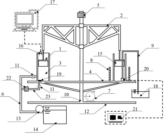
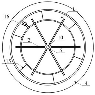
[0028] Such as figure 1 and figure 2 As shown, the embodiment of the device of the present invention is divided into a rotating water tank part, a circulating water body pipeline part, and an auxiliary monitoring device part.

[0029] The rotating water tank part includes an acrylic transparent water tank 3, a shear ring 1, a shear ring speed control rocker arm 2, a rotatable base 4, a rocker control frequency converter 5, a rotatable base control frequency converter 7, and a center liftable metal Rod 10, base support frame 12, paddle 15 and other parts. The acrylic transparent water tank is placed on the support frame of the base and is ring-shaped; the central liftable metal rod is connected to the speed control rocker arm of the shear force ring; the speed control rocker arm of the shear force ring is connected to the shear ring with blade force ring; the rocker arm control frequency converter and the rotatable base control frequency converter respectively control the sh...


PUM


Abstract

The invention discloses an observation device and method for a suspended sediment deposition structure in deceleration turbidity current. The device comprises a rotating water tank part, a circulating water body pipeline part and an auxiliary monitoring device part. The rotary water tank part comprises an acrylic transparent water tank, a shear ring, a shear ring rotating speed control rocker arm, a rotatable base, a rocker arm control frequency converter, a rotatable base control frequency converter, a center lifting metal rod, a base supporting frame, paddles and the like. The device is ingenious in structure, good in integrity, high in efficiency and low in device cost; physical modeling of the high-speed and strong-turbulence flow state of the turbidity current under the laboratory scale can be achieved, and meanwhile accurate conversion of the flow state is controlled. Large-particle-size sediment particles can be suspended in the annular water tank rotating at a high speed, viscous particles can be researched, and the flocculation capacity of the viscous particles is not damaged; by reversely rotating the bottom of the annular water tank, the secondary flow structure caused by the centrifugal effect can be reduced to the maximum extent, and the change of the shear stress of the tank bottom can be reduced to the minimum.

Description

technical field [0001] The invention relates to the field of sediment dynamics physical models, in particular to an observation device and method for suspended sediment deposition structures in decelerated turbid flows. Background technique [0002] Turbidity currents (sediment-laden currents) are widely developed in estuaries, deep seas and other environments. They are an important physical process for long-distance transportation of large-volume clastic sediments, nutrients and pollutants, and are very easy to form oil and gas resource reservoirs. At the same time, it will also greatly affect the ecological environment of deep sea basins; in addition, as a marine geological disaster, turbidity currents will directly threaten oil and gas exploration platforms and submarine communication cables. The key to clarifying its hydrodynamic process is to quantify the erosion-silting process of the near-bed sedimentary boundary layer, especially its vertical sedimentary bedding and ...

Claims


Application Information

Patent Timeline
Patent Type & Authority Applications(China)
IPC IPC(8): G01M10/00G01C11/00G01N21/84G01N21/85G01N15/02
CPCG01M10/00G01C11/00G01N21/84G01N21/85G01N15/02G01N2021/8411G01N2021/8592Y02A90/30
Inventor 林颖典何梦星韩东睿袁野平黄天炜贺治国姜书
Owner ZHEJIANG UNIV
Why Eureka
Try Eureka