
Acrylic polyurethane synthesis reactor

A technology of acrylic polyurethane and synthetic reactors, which is applied in chemical/physical/physical-chemical mobile reactors, chemical instruments and methods, chemical/physical/physical-chemical processes, etc., and can solve the problem of increasing cleaning personnel's damage to the inner wall of the synthetic cylinder Difficulty in cleaning, insufficient stirring of acrylic polyurethane emulsion, reduction of synthesis rate of acrylic polyurethane, etc., to achieve the effect of increasing synthesis rate and synthesis effect, reducing cleaning difficulty, and improving stirring effect

Pending Publication Date: 2022-06-07
苏桥
View PDF0 Cites 0 Cited by
  • Summary
  • Abstract
  • Description
  • Claims
  • Application Information

AI Technical Summary

Problems solved by technology

[0003] At present, the existing acrylic polyurethane synthesis reactor will encounter the following problems during use: a. The existing acrylic polyurethane synthesis reactor cannot adjust the stirring angle during the emulsion polymerization process, which makes the acrylic polyurethane emulsion stirring insufficient, thereby reducing the The synthetic rate of acrylic polyurethane; b. existing acrylic polyurethane synthesis reactor is in stirring polymerization process, and acrylic polyurethane emulsion is easily adhered on the synthetic cylinder inner wall, if not scraping off, will cause the waste of acrylic polyurethane emulsion, Increase the production cost, and also increase the difficulty for cleaning personnel to clean the inner wall of the synthetic cylinder

Method used


Image

  • Acrylic polyurethane synthesis reactor
  • Acrylic polyurethane synthesis reactor
  • Acrylic polyurethane synthesis reactor

Examples


Embodiment Construction

[0029] In order to make the technical means, creative features, goals and effects achieved by the present invention easy to understand, the present invention will be further described below in conjunction with specific embodiments.

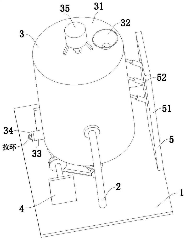
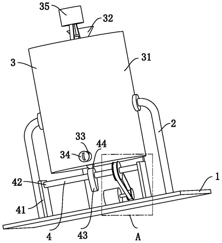
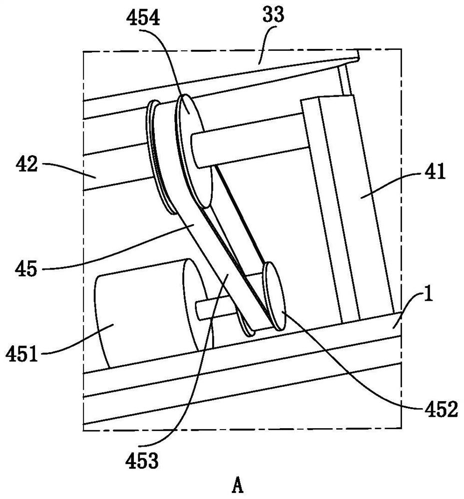
[0030] refer to Figure 1 to Figure 8 , an acrylic polyurethane synthesis reactor, comprising a bottom plate 1, a support rod 2, a synthesis component 3, a vibrating component 4 and a buffer component 5, the support rod 2 is symmetrically installed in the middle of the upper end of the bottom plate 1, and the upper end of the support rod 2 is rotationally connected There is a synthesis part 3, a vibration part 4 is arranged under the synthesis part 3, the lower end of the vibration part 4 is installed on the bottom plate 1, and a buffer part 5 is connected to the right side of the synthesis part 3;

[0031]The synthesis component 3 includes a synthesis cylinder 31, a feeding funnel 32, a discharge pipe 33, a rubber plug 34, an agitation unit 35, a...


PUM


Abstract

The invention relates to the technical field of chemical synthesis equipment, in particular to an acrylic polyurethane synthesis reactor which comprises a bottom plate, supporting rods, a synthesis component, a vibration component and a buffer component. The stirring unit not only can stir the acrylic polyurethane emulsion in the synthesis cylinder to increase the fluidity of the acrylic polyurethane emulsion so as to enable the acrylic polyurethane emulsion to react more fully, but also can drive the wall scraping unit to rotate and scrape the acrylic polyurethane emulsion adhered to the inner wall of the synthesis cylinder, so that the synthesis efficiency is improved. Therefore, the waste of the acrylic polyurethane emulsion is reduced, the production cost of the acrylic polyurethane is reduced, and meanwhile, the cleaning difficulty of cleaning personnel on the inner wall of the synthesis barrel is also reduced; the wall scraping units can also change the height of the stirring ring in the rotating process, so that the stirring angle of the flow stirring plate is changed, the reaction of the acrylic polyurethane emulsion is more sufficient, and the synthesis rate and the synthesis effect of the acrylic polyurethane are further improved.

Description

technical field [0001] The invention relates to the technical field of chemical synthesis equipment, in particular to an acrylic polyurethane synthesis reactor. Background technique [0002] The synthesis reactor is the equipment to realize the synthesis reaction process, which is widely used in chemical industry, oil refining, metallurgy, light industry and other fields. The acrylic polyurethane is a two-component self-drying coating composed of high-grade acrylic resin, pigments, additives and solvents as the hydroxyl component, and aliphatic isocyanate as the other component. It has excellent light resistance and outdoor resistance. Aging properties, acrylic polyurethanes can be produced by emulsion polymerization. [0003] At present, the existing acrylic polyurethane synthesis reactor will encounter the following problems during use: a. The existing acrylic polyurethane synthesis reactor cannot adjust the stirring angle during the emulsion polymerization process, which...

Claims


Application Information

Patent Timeline
Patent Type & Authority Applications(China)
IPC IPC(8): B01J19/28B01J19/00C08G18/08B08B9/087
CPCC08G18/08B01J19/285B01J19/0053B08B9/087
Inventor 苏桥张嘉伟
Owner 苏桥
Learn More